Dodge Journey: Description, Operation
DESCRIPTION

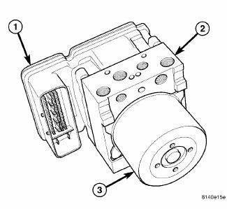
Fig. 2: Antilock Brake Module
- - ANTILOCK BRAKE MODULE (ABM)
- - HYDRAULIC CONTROL UNIT (HCU)
- - PUMP/MOTOR
The Antilock Brake Module (ABM) is a microprocessor-based device which monitors the antilock brake system (ABS) during normal braking and controls it when the vehicle is in an ABS stop or when in a traction control situation. The ABM utilizes a 47-way electrical connector on the vehicle wiring harness. The power source for the ABM is through the ignition switch in the RUN or ON position.
NOTE: The ABM is only separately serviceable for non-HSA (Hill Start Assist) equipped vehicles. Do not remove the ABM for vehicles equipped with HSA.
The ABM (1) is mounted to the HCU (2) as part of the Integrated Control Unit (ICU). The ICU is located in the engine compartment below the master cylinder on the front suspension cradle/crossmember. For information on the ICU.
OPERATION
The primary functions of the Antilock Brake Module (ABM) are to:
- Monitor the antilock brake system for proper operation.
- Detect wheel locking or wheel slipping tendencies by monitoring the speed of all four wheels of the vehicle.
- Control fluid modulation to the wheel brakes while the system is in an ABS mode.
- Store diagnostic information.
- Provide communication to the scan tool while in diagnostic mode.
- Illuminate the amber ABS warning indicator lamp.
- Illuminate the ESP function lamp in the message center on the instrument panel when a traction control event occurs.
- Illuminate the ESP function lamp when the amber ABS warning indicator lamp illuminates.
The ABM constantly monitors the antilock brake system for proper operation. If the ABM detects a fault, it will turn on the amber ABS warning indicator lamp and disable the antilock braking system. The normal base braking system will remain operational.
NOTE: If the vehicle is equipped with traction control, the ESP function lamp will illuminate anytime the amber ABS warning indicator lamp illuminates.
The ABM continuously monitors the speed of each wheel through the signals generated by the wheel speed sensors to determine if any wheel is beginning to lock. When a wheel locking tendency is detected, the ABM commands the ABM command coils to actuate. The coils then open and close the valves in the HCU that modulate brake fluid pressure in some or all of the hydraulic circuits. The ABM continues to control pressure in individual hydraulic circuits until a locking tendency is no longer present.
The ABM contains a self-diagnostic program that monitors the antilock brake system for system faults. When a fault is detected, the amber ABS warning indicator lamp is turned on and the fault diagnostic trouble code (DTC) is then stored in a diagnostic program memory. A latched fault will disable certain system functionality for the current ignition cycle. An unlatched fault will disable certain system functionality until the fault condition disappears. These DTC's will remain in the ABM memory even after the ignition has been turned off.
The DTC's can be read and cleared from the ABM memory by a technician using a scan tool. If not cleared with a scan tool, the fault occurrence and DTC will be automatically cleared from the ABM memory after the identical fault has not been seen during the next 3,500 miles. Drive-off may be required for the amber ABS warning indicator lamp to go out on the next ignition cycle.
ABM INPUTS
- Wheel speed sensors (four)
- Brake lamp switch
- Ignition switch
- System and pump voltage
- Ground
- ESP/BAS warning indicator lamp
- Diagnostic communication
ABM OUTPUTS
- Amber ABS warning indicator lamp actuation (via BUS)
- Red BRAKE warning indicator lamp actuation (via BUS)
- Instrument cluster (MIC) communication
- ESP/BAS warning indicator lamp
- Diagnostic communication
 Removal
LEFT-HAND DRIVE
NOTE: The ABM is only separately serviceable for non-HSA (Hill Start
Assist) equipped
vehicles. Do not remove the ABM for vehicles equipped with HSA.
1. Disconnect the nega ...
See also:
Description, Operation
DESCRIPTION
Fig. 418: Identifying Ignition Key/Switch Positions
- LOCK
- ACC
- ON
- START
The Brake Transmission Shifter/Ignition Interlock (BTSI) is a solenoid
operated system that ...
Installation
CAUTION: Be certain to adjust the refrigerant oil level when
servicing the A/C
refrigerant system. Failure to properly adjust the refrigerant
oil level will prevent the A/C system fro ...
Standard procedure
SPIRAL CELL BATTERY CHARGING
WARNING: Never exceed 14.4 volts when charging a spiral cell
battery. Personal
injury and/or battery damage may result.
Vehicles equipped with a diese ...

