Dodge Journey: Communication
DESCRIPTION
The primary on-board communication network between microprocessor-based electronic control modules in this vehicle is the Controller Area Network (CAN) data bus system. A data bus network minimizes redundant wiring connections; and, at the same time, reduces wire harness complexity, sensor current loads and controller hardware by allowing each sensing device to be connected to only one module (also referred to as a node). Each node reads, then broadcasts its sensor data over the bus for use by all other nodes requiring that data. Each node ignores the messages on the bus that it cannot use.
The CAN bus is a two-wire multiplex system. Multiplexing is any system that enables the transmission of multiple messages over a single channel or circuit. The CAN bus is used for communication between most vehicle nodes. However, in addition to the CAN bus network, certain nodes may also be equipped with a Local Interface Network (LIN) data bus. The LIN data bus is a single wire low-speed (9.6 Kbps) serial link bus used to provide direct communication between a LIN master module and certain switch or sensor inputs.
There are actually three separate CAN bus systems used in the vehicle. They are designated: the CAN-Interior (also known as CAN Interior High Speed/IHS), the CAN-C and the Diagnostic CAN-C. The CAN-Interior and CAN-C systems provide on-board communication between all nodes in the vehicle. The CAN-C is the faster of the two systems providing near real-time communication (500 Kbps). The CAN-C is used typically for communications between more critical nodes, while the slower (125 Kbps) CAN-Interior system is used for communications between less critical nodes.
The added speed of the CAN data bus is many times faster than previous data bus systems. This added speed facilitates the addition of more electronic control modules or nodes and the incorporation of many new electrical and electronic features in the vehicle.
The Diagnostic CAN-C bus is also capable of 500 Kbps communication, and is sometimes informally referred to as the CAN-D system to differentiate it from the other high speed CAN-C bus. The Diagnostic CAN-C is used exclusively for the transmission of diagnostic information between the Totally Integrated Power Module/Central GateWay (TIPM or TIPMCGW) and a diagnostic scan tool connected to the industry-standard 16-way Data Link Connector (DLC) located beneath the instrument panel on the driver side of the vehicle.
The TIPM is located in the engine compartment near the battery. The central CAN gateway or hub module integral to the TIPM is connected to all three CAN buses. This gateway physically and electrically isolates the CAN buses from each other and coordinates the bi-directional transfer of messages between them.
OPERATION
The Controller Area Network (CAN) data bus allows all electronic modules or nodes connected to the bus to share information with each other. Regardless of whether a message originates from a module on the lower speed CAN-Interior (also known as CAN Interior High Speed/IHS) bus or on the higher speed CAN-C or CAN-D bus, the message structure and layout is similar, which allows the Totally Integrated Power Module/Central GateWay (TIPM or TIPMCGW) to process and transfer messages between the CAN buses. The TIPM also stores a Diagnostic Trouble Code (DTC) for certain bus network faults.
All modules (also referred to as nodes) transmit and receive messages over one of these buses. Data exchange between nodes is achieved by serial transmission of encoded data messages. Each node can both send and receive serial data simultaneously. Each digital bit of a CAN bus message is carried over the bus as a voltage differential between the two bus circuits which, when strung together, form a message. Each node uses arbitration to sort the message priority if two competing messages are attempting to be broadcast at the same time.
The ElectroMechanical Instrument Cluster (EMIC) (also known as the Cab Compartment Node/CCN) is the Local Interface Network (LIN) master module in this vehicle and it gathers information from the compass module, the instrument panel switch bank, the Steering Control Module (SCM), and the Heated Seat Module (HSM) through the LIN data bus. There is also LIN bus communication between the individual Tire Pressure Monitor (TPM) transponders and the Wireless Ignition Node (WIN). Both the EMIC and the WIN either act directly upon the information received through the LIN data bus, relay the information to other nodes in the vehicle using electronic messages placed on the CAN bus, or both.
The voltage network used to transmit messages requires biasing and termination. Each module on the CAN bus network provides its own biasing and termination. There are two types of nodes used in the CAN bus network.
On the CAN-C or the IHS bus, a dominant node has a 120 ohm termination resistance while a non-dominant (or recessive) node has about a 2500 to 3000 ohm (2.5 to 3.0 kilohm) termination resistance. The dominant nodes on the CAN-C bus are the WIN and the Powertrain Control Module (PCM). The dominant nodes on the IHS bus are the EMIC and the TIPM.
The termination resistance of two dominant nodes is combined in parallel to provide a total of about 60 ohms.
This resistance value may vary somewhat by application, depending upon the number of non-dominant nodes on the bus. On the CAN-D bus (or Diagnostic CAN-C) all of the 60 ohm termination resistance is present in the Central GateWay (TIPMCGW).
NOTE: All measurement of termination resistance is done with the vehicle battery disconnected.
The communication protocol being used for the CAN data bus is a non-proprietary, open standard adopted from the Bosch CAN Specification 2.0b. The CAN-C is the faster of the two primary buses in the CAN bus system, providing near real-time communication (500 Kbps).
The CAN bus nodes are connected in parallel to the two-wire bus using a twisted pair, where the wires are wrapped around each other to provide shielding from unwanted electromagnetic induction, thus preventing interference with the relatively low voltage signals being carried through them. The twisted pairs have between 33 and 50 twists per meter (yard). While the CAN bus is operating (active), one of the bus wires will carry a higher voltage and is referred to as the CAN High or CAN bus (+) wire, while the other bus wire will carry a lower voltage and is referred to as the CAN Low or CAN bus (-) wire. Refer to the CAN BUS VOLTAGES chart.
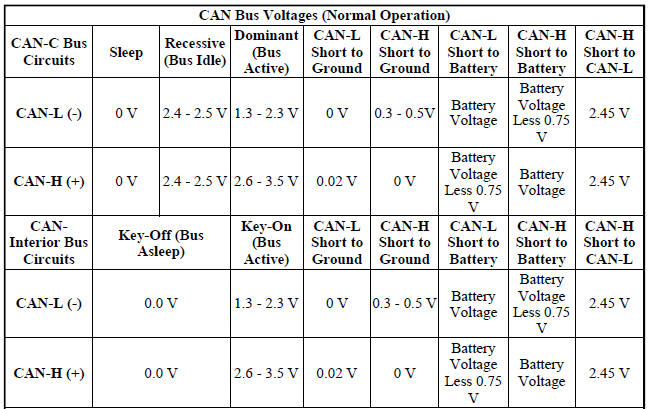
Notes: All measurements taken between node ground and CAN terminal with a standard DVOM.
DVOM will display average network voltage.
Total resistance of CAN-C network can also be measured (60 ohms). Total resistance of CAN-Interior network varies, depending upon the number of optional non-dominant nodes on the bus. CAN-Interior total resistance should range between about 60 ohms with the minimal number of nodes, to about 42 ohms with the maximum number of nodes.
In order to minimize the potential effects of Ignition-OFF Draw (IOD), the CAN-Interior network employs a sleep strategy. However, a network sleep strategy should not be confused with the sleep strategy of the individual nodes on that network, as they may differ. For example: The CAN-C bus network is awake only when the ignition switch is in the ON or START positions; however, the TIPM, which is on the CAN-C bus, may still be awake with the ignition switch in the ACCESSORY or UNLOCK positions. The integrated circuitry of an individual node may be capable of processing certain sensor inputs and outputs without the need to utilize network resources.
The CAN-Interior bus network remains active until all nodes on that network are ready for sleep. This is determined by the network using tokens in a manner similar to polling. When the last node that is active on the network is ready for sleep, and it has already received a token indicating that all other nodes on the bus are ready for sleep, it broadcasts a bus sleep acknowledgment message that causes the network to sleep. Once the CAN-Interior bus network is asleep, any node on the bus can awaken it by transmitting a message on the network. The TIPM will keep either the CAN-Interior or the CAN-C bus awake for a timed interval after it receives a diagnostic message for that bus over the Diagnostic CAN-C bus.
In the CAN system, available options are configured into the TIPM at the assembly plant, but additional options can be added in the field using the diagnostic scan tool. The configuration settings are stored in non-volatile memory. The TIPM also has two 64-bit registers, which track each of the as-built and currently responding nodes on the CAN-Interior and CAN-C buses. The TIPM stores a Diagnostic Trouble Code (DTC) in one of two caches for any detected active or stored faults in the order in which they occur. One cache stores powertrain (P-Code), chassis (C-Code) and body (B-Code) DTCs, while the second cache is dedicated to storing network (U-Code) DTCs.
If there are intermittent or active faults in the CAN network, a diagnostic scan tool connected to the Diagnostic CAN-C bus through the 16-way Data Link Connector (DLC) may only be able to communicate with the TIPM.
To aid in CAN network diagnosis, the TIPM will provide CAN-Interior and CAN-C network status information to the scan tool using certain diagnostic signals. In addition, the transceiver in each node on the CAN-C bus will identify a bus off hardware failure , while the transceiver in each node on the CAN-Interior bus will identify a general bus hardware failure . The transceivers for some CAN-Interior nodes will also identify certain failures for both CAN-Interior bus signal wires.
 Standard procedure
MODULE/PROGRAMMING ORDER REPLACEMENT GUIDE
MODULE PROGRAMMING
The Wireless Ignition Node (WIN) controls the Vehicle Theft Security System (VTSS),
Remote Keyless Entry
(RKE). When a Powertrain ...
 Connector, data link
DESCRIPTION
Fig. 1: Data Link Connector
The Data Link Connector (DLC) (2) is a 16-way molded plastic connector
insulator on a dedicated take out of
the instrument panel wire harness. This conne ...
See also:
MEDIA CENTER 130 (RES/RSC) — AM/FM STEREO RADIO WITH CD PLAYER (MP3 AUX
JACK) AND SIRIUS RADIO
NOTE: The radio sales code is located on the lower right
side of the radio faceplate.
RES/RSC Radio
Operating Instructions — Radio Mode
NOTE: The ignition switch must be in the ON or ACC
posi ...
Antenna, satellite, audio, video
ANTENNA, SATELLITE, AUDIO
DESCRIPTION
Fig. 3: Satellite Audio
If the vehicle is equipped with satellite audio, a combined antenna for AM/FM
and satellite is used. For
removal. See Removal and ...
Disassembly
HOUSING-AIR DISTRIBUTION
NOTE: The air distribution housing must be removed from the HVAC
housing and
disassembled for service of the blend-air and mode-air doors.
NOTE: LHD model with A/C ...
