Dodge Journey: Switch, remote radio
DESCRIPTION
Remote radio control switches are rocker-type switch units are mounted in the upper spoke covers of the rear (instrument panel side) steering wheel trim cover. The switch unit on the left side is the seek switch and has seek up, seek down, and preset station advance switch functions. The switch unit on the right side is the volume control switch and has volume up, volume down, and mode advance switch functions.
The two remote radio switch units are each retained in a mounting hole located on opposite sides of the rear steering wheel trim cover by four integral snap features. A plastic bracket on the back of each switch unit provides additional support for the unit by extending towards the center of the steering wheel where it is clamped between the steering wheel armature and the steering wheel rear trim cover mounting boss by the trim cover mounting screw.
The two remote radio switch units share a common steering wheel wire harness with the vehicle speed control switches. The steering wheel wire harness is connected to the instrument panel wire harness through the clock-spring.
DIAGNOSIS AND TESTING
REMOTE SWITCHES
Any diagnosis of the Audio system should begin with the use of the scan tool. For information on the use of the scan tool, refer to the appropriate Diagnostic Service information.
For complete circuit diagrams, refer to SYSTEM WIRING DIAGRAMS .
WARNING: Disable the airbag system before attempting any steering wheel, steering column, seat belt tensioner, side airbag or instrument panel component diagnosis or service. Disconnect and isolate the negative battery (ground) cable. Wait two minutes for the airbag system capacitor to discharge before performing further diagnosis or service. This is the only sure way to disable the airbag system. Failure to follow these instructions may result in accidental airbag deployment and possible serious or fatal injury.
1. Disconnect and isolate the battery negative cable. Remove the remote radio switch(es) from the steering wheel.
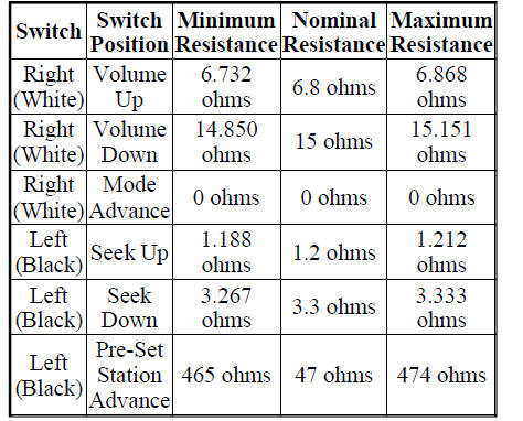
2. Use an ohmmeter to check the switch resistances as shown in REMOTE RADIO SWITCH TEST. If the remote radio switch resistances check OK , go to 3. If not OK, replace the faulty switch.
REMOTE RADIO SWITCH TEST
3. Reconnect the battery negative cable. Turn the ignition switch to the ON position. Check for 5 volts at the radio control circuit cavities of the steering wheel wire harness connectors for both remote radio switches.
If OK, refer to BODY . If not OK, repair the circuit as required.
REMOVAL
WARNING: Disable the airbag system before attempting any steering wheel, steering column, seat belt tensioner, side airbag or instrument panel component diagnosis or service. Disconnect and isolate the negative battery (ground) cable. Wait two minutes for the airbag system capacitor to discharge before performing further diagnosis or service. This is the only sure way to disable the airbag system. Failure to follow these instructions may result in accidental airbag deployment and possible serious or fatal injury.
Fig. 20: Removing / Installing Driver Side Airbag Module
1. Disconnect and isolate the battery negative cable.
2. Remove the driver side airbag module from the steering wheel.

Fig. 21: Retainers, Horn Connector And Button Assembly
3. Disconnect the horn connector (3).
4. Remove retainers (1) and remove the horn button assembly (2).

Fig. 22: Speed Control Switch
5. Remove the speed control switch (3).

Fig. 23: Radio Switches
6. Disconnect the radio switches (1).
7. From the inside of the steering wheel rear trim cover, press firmly and evenly outward on the back of the switch to disengage the four snap features that secure the switch to the inside of the mounting hole.
8. From the outside of the steering wheel rear trim cover, remove the remote radio switch from the trim cover mounting hole.
INSTALLATION
WARNING: Disable the airbag system before attempting any steering wheel, steering column, seat belt tensioner, side airbag or instrument panel component diagnosis or service. Disconnect and isolate the negative battery (ground) cable. Wait two minutes for the airbag system capacitor to discharge before performing further diagnosis or service. This is the only sure way to disable the airbag system. Failure to follow these instructions may result in accidental airbag deployment and possible serious or fatal injury.
Fig. 24: Radio Switches
1. Position the remote radio switch to the mounting hole on the outside of the steering wheel rear trim cover.
Be certain that the connector receptacle is oriented toward the bottom of the switch and pointed toward the center of the steering wheel.
2. Press firmly and evenly on the remote radio switch until each of the switch snap features is fully engaged in the mounting hole of the steering wheel rear trim cover.
3. Reconnect the steering wheel wire harness connector to the connector receptacle of the remote radio switch (1).
Fig. 25: Speed Control Switch
4. Install the speed control switch (3).
Fig. 26: Retainers, Horn Connector And Button Assembly
5. Install the horn button assembly (2) and install the three retainers (1).
6. Connect the horn connector (3).

Fig. 27: Removing / Installing Driver Side Airbag Module
7. Install the driver side airbag module to the steering wheel.
8. Connect the battery negative cable.
 Speaker
OPERATION
Two wires connected to each speaker, one feed circuit (+) and one return
circuit (-), allow the audio output signal electrical current to flow through
the voice coil. The wiring informa ...

See also:
Actuator, blend door, rear
DESCRIPTION
Fig. 47: Rear Actuator Description
The blend door actuator (1) for the rear heating-A/C system is a reversible,
12 volt direct current (DC), servo
motor. The rear blend door actuato ...
Holding clutches
DESCRIPTION
Fig. 356: Identifying 2/4 & Low/Reverse Clutches & Planetary Geartrain
Components
- FRONT PLANET CARRIER/REAR ANNULUS
- 2/4 CLUTCH
- L/R CLUTCH
- REAR PLANET CARRIER ...
Module, satellite video
REMOVAL
1. Disconnect and isolate the negative battery cable.
2. Move the front passenger seat to the most forward position.
Fig. 8: Antenna & Electrical Connectors
3. Disconnect the three ...
