Dodge Journey: Removal, Installation
REMOVAL

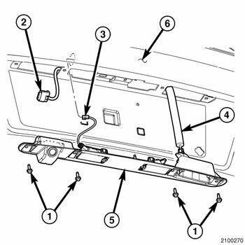
Fig. 6: Backup Camera & Liftgate & Lights
1. Disconnect the negative battery cable.
2. Remove the four retainers (1) holding the lightbar (5) to the liftgate (6).
3. Using a trim stick or equivalent, release the lightbar (5) from the clips.
4. Disconnect the electrical connectors from the backup camera (2) and the lights (3).
5. Disconnect the liftgate release cable (4) from the lightbar (5).
6. Remove the retainer from the back of the camera.
7. Unclip the camera cover from the lightbar.
8. Remove the camera mounting retainers.
9. Remove the camera from the lightbar.
INSTALLATION

Fig. 7: Backup Camera & Liftgate & Lights
1. Install the camera to the lightbar.
2. Install the camera mounting retainers.
3. Clip the camera cover to the lightbar.
4. Install the retainer to the back of the camera.
5. Connect the liftgate release cable (4) to the lightbar (5).
6. Connect the electrical connectors to the backup camera (2) and the lights (3).
7. Install the lightbar to the tailgate.
8. Install the four retainers (1) holding the lightbar (5) to the liftgate (6).
9. Connect the negative battery cable.
 Diagnosis and Testing
Rear Camera
The hardwired circuits of the Rear View Camera (RVC) and those between the
RVC and the radio receiver may
be diagnosed using conventional diagnostic tools and procedures.
The wiring ...
 Module, satellite video
REMOVAL
1. Disconnect and isolate the negative battery cable.
2. Move the front passenger seat to the most forward position.
Fig. 8: Antenna & Electrical Connectors
3. Disconnect the three ...
See also:
Description, Operation
DESCRIPTION
Fig. 1: Identifying 41TE Automatic Transaxle Components
- TRANSAXLE CASE
- TORQUE CONVERTER
- OIL PUMP
- INPUT SPEED SENSOR
- UNDERDRIVE CLUTCH
- OVERDRIVE CLUTCH
- REVE ...
Removal
2.4L
Fig. 59: Identifying Ignition Coil Electrical Connectors
NOTE: Prior to removing coil, spray compressed air around coil top to
make sure no
dirt drops into the spark plug tube.
1. ...
Pump, water
Description
2.4L
Fig. 80: WATER PUMP - WORLD ENGINE
- ACCESSORY DRIVE BELT
- WATER PUMP PULLEY
- WATER PUMP
The water pump (3) on the world engine is attached to the water pump adapter ...
