Dodge Journey: Description, Operation
DESCRIPTION

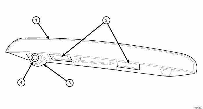
Fig. 4: Rear View Camera
The Rear View Camera (RVC) (4) (also known as ParkView), is a camera on chip device utilizing Complementary Metal Oxide Semiconductor (CMOS) technology. CMOS technology is used for a wide variety of digital or analog circuits. In this application, it supports the analog image sensor of the RVC. The RVC function is to provide a wide angle video image of the area behind the vehicle, including areas that might not be normally visible from the seated position of the vehicle operator, only while the transaxle gear selector is in the Reverse position. This video image then displays to the vehicle operator within the display screen of the audio system receiver unit near the center of the instrument panel.
The RVC is intended to be an auxiliary viewing aid and is not promoted as an obstacle detection or safety device. It does not remove vehicle operator responsibility to recognize and obey official traffic laws or regulations or to take sensible precautions and care to avoid pedestrians, other vehicle traffic or both fixed and moving obstacles through the habitual use of safe and defensive driving techniques.
The RVC is located on the underside of the light bar (1) mounted above the license plate tub on the vehicle liftgate. The camera lens is visible just to the left of the vehicle center line, while the body of the camera and the camera connections are concealed within the light bar above a camera mounting bracket (3), to which the camera is secured with three screws. The camera mounting bracket secures to the light bar assembly to the left of the left license plate lamp (2) with two additional screws. A light bar wire harness routes through a rubber grommet into the interior of the liftgate where it connects the RVC and both license plate lamps to the vehicle electrical system through a dedicated take out and connector of the liftgate wire harness.

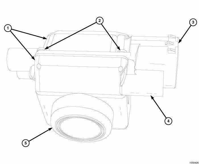
Fig. 5: Camera Image Sensor & Electronics
The camera image sensor and electronics are sealed and protected within a two-piece die cast zinc housing (1), held together by four screws (2). The camera lens (5) extends from the lower surface of the housing and an integral connector receptacle (3) containing five terminal pins that extends from the right side of the housing.
Additionally, there are three mounting bosses (4) integral to the camera housing, two on the left side and one on the right. The mounting bosses receive the three self-tapping screws securing the unit to the camera bracket.
Hardwired circuitry connects the RVC to the electrical system of the vehicle. These hardwired circuits are integral to several wire harnesses, which routes throughout the vehicle and retained by many different methods.
These circuits may be connected to each other and to the vehicle electrical system through the use of a combination of soldered splices, splice block connectors, and many different types of wire harness terminal connectors and insulators. The wiring information includes wiring diagrams, proper wire and connector repair procedures, further details on wire harness routing and retention, as well as pin-out and location views for the various wire harness connectors, splices and grounds.
The RVC cannot be adjusted or repaired. If the RVC is damaged or ineffective, it must be replaced.
OPERATION
The Rear View Camera (RVC) is powered by a battery feed received through the backup lamp switch output circuit from the Totally Integrated Power Module (TIPM) so that is only active when the transaxle is shifted into the REVERSE position. In addition, the radio receiver monitors messages on the Controller Area Network (CAN) data bus to determine the selected transaxle gear and overrides any other display to show the RVC video output, whenever it detects that the transaxle is in REVERSE. A momentary blank video display screen immediately following the gearshift transition into the REVERSE position is considered normal operation. The camera electronics receive a path to ground at all times through a takeout and eyelet terminal of the liftgate wire harness that is secured by a ground screw to the right side of the liftgate inner panel.
The output of the camera is a video signal compatible to the National Television System Committee (NTSC) standard composite video M format, or NTSC-M. The video signal is delivered to the radio video display unit through the entire length of the vehicle by camera signal and the camera return circuits that are arranged as a twisted pair, with an additional grounded foil jacket to protect the video signal from corruption due to stray radiated signals within the vehicle environment. The ground shield is terminated only at the video display (radio) end, not at the camera. Portions of these video signal wires are contained within the liftgate lightbar wire harness, the liftgate wire harness, the body wire harness and a jumper harness located between the radio and the body harness connector below the instrument panel at the right cowl side inner panel.
 Camera
...
 Diagnosis and Testing
Rear Camera
The hardwired circuits of the Rear View Camera (RVC) and those between the
RVC and the radio receiver may
be diagnosed using conventional diagnostic tools and procedures.
The wiring ...
See also:
Standard procedure
PARKING BRAKE CABLE TENSION RELEASE - FOOT LEVER
Use the following procedure to release the tension from the parking brake
cables and the automatic adjuster in
the parking brake lever (pedal) mech ...
Tray, battery
DESCRIPTION
The battery is placed and secured in a stamped steel battery tray. The
battery tray is located in the left front side
of the vehicle, just ahead of the left front wheel and tire assemb ...
Sensor, variable line pressure
DESCRIPTION
Fig. 390: Identifying Variable Line Pressure Sensor
- PRESSURE CONTROL SOLENOID
- LINE PRESSURE SENSOR
- SHOULDER SCREW
- VARIABLE LINE PRESSURE HEADER
- MANUAL SHAFT
- SC ...
