Dodge Journey: TIRE SAFETY INFORMATION
Tire Markings
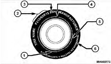
1 — U.S. DOT Safety Standards Code (TIN).
4 — Maximum Load.
NOTE:
• P (Passenger) - Metric tire sizing is based on U.S.
design standards. P-Metric tires have the letter “P”
molded into the sidewall preceding the size designation.
Example: P215/65R15 95H.
• European-Metric tire sizing is based on European
design standards. Tires designed to this standard have
the tire size molded into the sidewall beginning with
the section width. The letter P is absent from this tire
size designation. Example: 215/65R15 96H.
• LT (Light Truck) - Metric tire sizing is based on U.S.
design standards. The size designation for LT-Metric
tires is the same as for P-Metric tires except for the
letters “LT” that are molded into the sidewall preceding
the size designation. Example: LT235/85R16.
• Temporary spare tires are high-pressure compact
spares designed for temporary emergency use only.
Tires designed to this standard have the letter “T”
molded into the sidewall preceding the size designation.
Example: T145/80D18 103M.
• High flotation tire sizing is based on U.S. design
standards, and it begins with the tire diameter molded
into the sidewall. Example: 31x10.5 R15 LT.
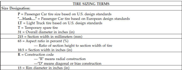
Tire Sizing Chart
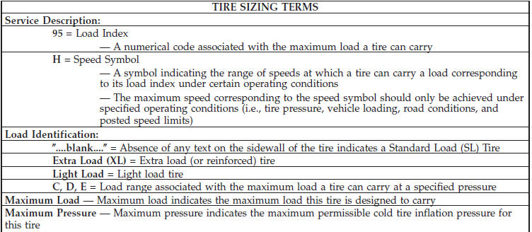
TIRE SIZING TERMS
Tire Identification Number (TIN)
The TIN may be found on one or both sides of the tire, however, the date code may only be on one side. Tires with white sidewalls will have the full TIN, including the date code, located on the white sidewall side of the tire.
Look for the TIN on the outboard side of black sidewall tires as mounted on the vehicle. If the TIN is not found on the outboard side, then you will find it on the inboard side of the tire.
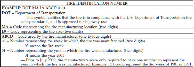
TIRE IDENTIFICATION NUMBER
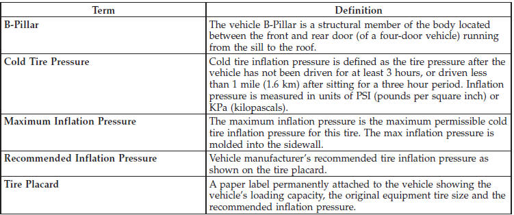
Tire Terminology and Definitions
Tire Loading and Tire Pressure
Tire Placard Location
NOTE: The proper cold tire inflation pressure is listed on the driver’s side B-Pillar.
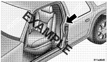
Tire Placard Location
Tire and Loading Information Placard
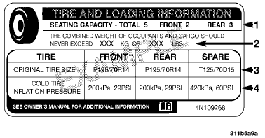
Tire and Loading Information Placard
This placard tells you important information about the: 1) number of people that can be carried in the vehicle 2) total weight your vehicle can carry 3) tire size designed for your vehicle 4) cold tire inflation pressures for the front, rear, and spare tires.
Loading
The vehicle maximum load on the tire must not exceed the load carrying capacity of the tire on your vehicle. You will not exceed the tire’s load carrying capacity if you adhere to the loading conditions, tire size, and cold tire inflation pressures specified on the Tire and Loading Information placard and in the “Vehicle Loading” section of this manual.
NOTE: Under a maximum loaded vehicle condition, gross axle weight ratings (GAWRs) for the front and rear axles must not be exceeded. For further information on GAWRs, vehicle loading, and trailer towing, refer to “Vehicle Loading” in this section.
To determine the maximum loading conditions of your vehicle, locate the statement “The combined weight of occupants and cargo should never exceed XXX kg or XXX lbs.” on the Tire and Loading Information placard. The combined weight of occupants, cargo/luggage and trailer tongue weight (if applicable) should never exceed the weight referenced here.
Steps for Determining Correct Load Limit
1. Locate the statement “The combined weight of occupants and cargo should never exceed XXX kg or XXX lbs” on your vehicle’s placard.
2. Determine the combined weight of the driver and passengers that will be riding in your vehicle.
3. Subtract the combined weight of the driver and passengers from XXX kg or XXX lbs.
4. The resulting figure equals the available amount of cargo and luggage load capacity. For example, if “XXX” amount equals 1,400 lbs (635 kg) and there will be five 150 lb (68 kg) passengers in your vehicle, the amount of available cargo and luggage load capacity is 650 lbs (295 kg) (since 5 x 150 = 750, and 1400 – 750 = 650 lbs [295 kg]).
5. Determine the combined weight of luggage and cargo being loaded on the vehicle. That weight may not safely exceed the available cargo and luggage load capacity calculated in Step 4.
6. If your vehicle will be towing a trailer, load from your trailer will be transferred to your vehicle. Consult this manual to determine how this reduces the available cargo and luggage load capacity of your vehicle.
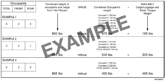
NOTE: The following table shows examples on how to calculate total load, cargo/luggage, and towing capacities of your vehicle with varying seating configurations and number and size of occupants. This table is for illustration purposes only and may not be accurate for the seating and load carry capacity of your vehicle.
NOTE: For the following example, the combined weight of occupants and cargo should never exceed 865 lbs (392 kg).
WARNING:
Overloading of your tires is dangerous. Overloading
can cause tire failure, affect vehicle handling, and
increase your stopping distance. Use tires of the
recommended load capacity for your vehicle. Never
overload them.
 ELECTRONIC BRAKE CONTROL SYSTEM
Your vehicle is equipped with an advanced electronic
brake control system commonly referred to as ESP. This
system includes Anti-Lock Brake System (ABS), Brake
Assist System (BAS), Traction Control ...
 TIRES — GENERAL INFORMATION
Tire Pressure
Proper tire inflation pressure is essential to the safe and
satisfactory operation of your vehicle. Three primary
areas are affected by improper tire pressure:
Safety
WARNING:
• ...
See also:
ELECTRONIC VEHICLE INFORMATION CENTER (EVIC) — IF EQUIPPED
The Electronic Vehicle Information Center (EVIC) features
a driver-interactive display. It is located in the
instrument cluster below the fuel and temperature
gauges. Vehicles equipped with steerin ...
Synchronizer
DISASSEMBLY
Place synchronizer in a clean shop towel and wrap. Press on inner hub.
Carefully open up shop towel and
remove springs, balls, keys, hub, and sleeve.
CLEANING
Do not attempt to clean ...
Relay, heater unit
DESCRIPTION
Fig. 320: Standard ISO-Type Relay
Three relays (1) are used for the electric positive temperature coefficient (PTC)
heater system when equipped
with the 2.0L diesel engine. The rela ...
