Dodge Journey: VIDEO ENTERTAINMENT SYSTEM (VES)™ — IF EQUIPPED
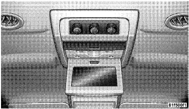
The optional Video Entertainment System (VES)™ includes the following components for rear seat entertainment: • A diagonal 8 in (20 cm) Liquid Crystal Display (LCD) screen integrated into the center overhead console.
The screen features brightness control for optimum daytime and nighttime viewing.
• The LCD Screen swings down from the console to allow the rear seat passenger(s) to view the display.

VES™ with Rear HVAC Controls
• The touch screen radio and DVD player controls allow front seat operation for easy setup in the case of younger rear seat passengers.
• A battery-powered infrared remote control that snaps into a molded compartment in the center console.
• Two wireless infrared headsets allow rear seat passengers to listen to the same or individual audio sources.
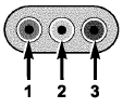
 Audio/Video RCA Jacks (AUX
Jacks)
on the rear of the center console enable
the monitor to display video directly
from a video camera, connect video
games for display on the screen, or
play music directly from an MP3
player.
1. Video in (yellow).
2. Left audio in (white).
3. Right audio in (red).
NOTE: Refer to your “Video Entertainment System (VES)™ User Manual” for detailed operating instructions.
 Uconnect™ Multimedia (SIRIUS BACKSEAT TV™) — IF EQUIPPED
Satellite video uses direct satellite receiver broadcasting
technology to provide streaming video. The subscription
service provider is SIRIUS Satellite Radio. SIRIUS Backseat
TV™ offers three vi ...
 UNIVERSAL CONSUMER INTERFACE (UCI) 0.5 — IF EQUIPPED
NOTE: This section is for sales code RES/REL and
REQ/RET radios only with uconnect . For sales code
RBZ/REN/REZ touch screen radio and REU/REX/RE1
radio, refer to the separate User’s Manual.
Thi ...
See also:
Disassembly, Assembly
Disassembly
NOTE: Before disassembling the brake caliper, remove it from the
vehicle.
NOTE: Before disassembling the brake caliper, clean and inspect it.
WARNING: Under no condition sh ...
Fluid
Diagnosis and Testing
BRAKE FLUID CONTAMINATION
Indications of fluid contamination are swollen or deteriorated rubber parts.
Swelling indicates the presence of
petroleum in the brake fluid.
To ...
Hub and bearing
DESCRIPTION
Fig. 31: Front Hub And Bearing Mounting
The front wheel bearing and wheel hub of this vehicle are a one piece sealed
unit or hub and bearing unit type
assembly.
The hub and beari ...
