Dodge Journey: Lever, shift
REMOVAL
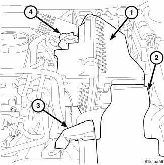
Fig. 183: Air Cleaner And Inlet Tube
Remove the engine cover.
1. Disconnect battery negative cable.
2. Remove air inlet tube (2) and air cleaner assembly (4).
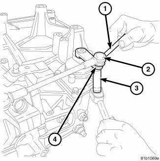
Fig. 184: Nut Crossover Rod To Shift Lever
3. Remove the nut (4) holding the crossover rod (2) to the shift lever. Be sure to use a wrench (1) to hold the ball stud to prevent it from rotating in the shift lever.

Fig. 185: Anti-Rotation Bolt
4. Loosen and remove shift tower ball for the shift detent (5).
5. Loosen and remove shift lock ball for the select detent (3).
6. Loosen and remove shift guide pin (2).

Fig. 186: Shift Lever Assembly Bolts
7. Remove the bolts holding the shift lever assembly to the transmission.

Fig. 187: Shift Lever Assembly
8. Remove the shift lever assembly from the transmission case.
INSTALLATION
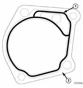
Fig. 188: Sealer
1. Add MOPAR Gasket Maker, Loctite 518, or equivalent around inside of all holes and on mating flange.
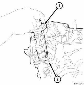
Fig. 189: Shift Lever Assembly
2. Install the shift lever assembly (1) into the transmission case (2).
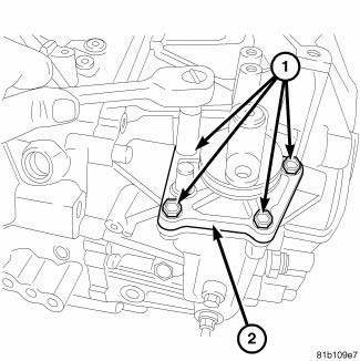
Fig. 190: Shift Lever Assembly Bolts
3. Install the new bolts (1) holding the shift lever assembly (2) to the transmission and tighten to 19 N.m (168 in. lbs.)
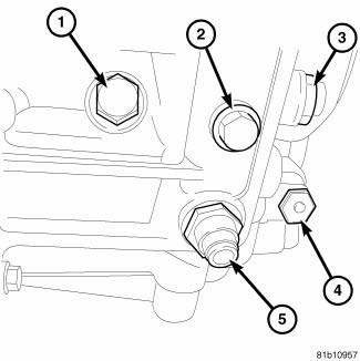
Fig. 191: Anti-Rotation Bolt
4. Install new shift tower lock ball for shift detent (5) and tighten to 29 N.m (277 in. lbs.).
5. Install new shift lock ball for the select detent (3) and tighten to 39 N.m (345 in. lbs.).
6. Install new shift tower shift guide pin (2) and tighten to 30 N.m (277 in. lbs.).

Fig. 192: Nut Crossover Rod To Shift Lever
CAUTION: Be sure to verify bracket position after installation.
7. Install the nut (4) holding the crossover rod (2) to the shift lever. Be sure to use a wrench (1) to hold the ball stud to prevent it from rotating in the shift lever tighten to 12 N.m (106 in. lbs.).
 Input shaft, transmission
DISASSEMBLY
Fig. 175: Snap Ring At Input Shaft
1. Remove the snap ring (2) that retains the input shaft bearing and sixth
gear to the shaft.
Fig. 176: Press Bearing From Input Shaft
2. Using ...
 Mechanism, gearshift
REMOVAL
Fig. 193: Shift Cables To Shifter
1. Detach gear shift boot from console.
2. Remove the center console assembly.
3. Remove rear power window switch (if equipped) and disconnect ha ...
See also:
Removal
WARNING: Disable the airbag system before attempting any steering
wheel, steering
column, or instrument panel component diagnosis or service. Disconnect
and isolate the battery negati ...
Removal, Installation
REMOVAL
WARNING: Disable the airbag system before attempting any steering
wheel, steering
column, or instrument panel component diagnosis or service. Disconnect
and isolate the negat ...
Description, Operation
DESCRIPTION
Fig. 265: A/C Expansion Valve Description KA
The A/C expansion valve controls the amount of refrigerant entering the A/C
evaporator. The A/C expansion
valve is of a thermostatic exp ...
