Dodge Journey: Cable, gearshift control
REMOVAL
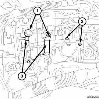
Fig. 161: Shift Cables & Bracket
1. Remove the shifter.
2. Raise hood.
3. Remove the resonator.
4. Remove engine cover.
5. Remove air cleaner assembly.
6. Disconnect negative battery cable.
7. Disconnect cables (1) from the shift levers at the transaxle.
CAUTION: Pry up with equal force on both sides of shifter cable isolator bushings to avoid damaging cable isolator bushings or damaging levers.

Fig. 162: Shift Cables To Shifter
8. Remove cable retaining clips and remove cables (1) from bracket (5).
9. Remove cables at shifter.
10. Remove the Occupant Restraint Controller (ORC).
11. Remove rubber grommet (4) at floor pan.
12. Remove cable assembly (1) from vehicle.
INSTALLATION

Fig. 163: Shift Cables & Bracket
CAUTION: Gearshift cable bushings must not be lubricated or the bushings will swell and split.
1. Install cable assembly through floor pan opening until grommet is seated.
2. Route transaxle end of cable assembly into engine compartment and over transaxle assembly.
3. Connect cables (1) to the shift levers (3) at the transaxle.
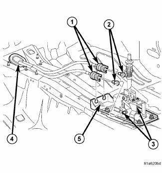
Fig. 164: Shift Cables To Shifter
4. Install gearshift cables to mounting bracket (5) and fasten with NEW clips (2). Make sure clips are installed flush to bracket.
5. Install cables (2) to shifter levers (3).
6. Install ORC.
7. Install the air cleaner assembly.
8. Connect battery cables.
ADJUSTMENT
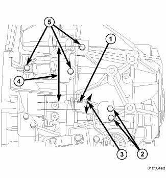
Fig. 165: Shift Adjustment
Increase the (4) distance to eliminate 2nd gear downshift blocking condition (3-2, or 4-2 blocking).
NOTE: Must verify reverse shift after adjusting.
Decrease the distance if shifter can not engage reverse.
1. Loosen select lever bracket bolts (2).
2. Adjust gage length fore/aft by pivoting bracket and securing. Torque to 21.4 +/- 5.2 N.m.
 Installation
Fig. 137: Rear Mount Bracket
1. If transmission brackets were removed or transmission was replaced install
the rear mount bracket and
tighten (1) to 100 N.m (74 ft. lbs.).
Fig. 138: Front Mou ...
 Differential, transaxle
DESCRIPTION
Fig. 166: Differential Assembly
- RING GEAR
- PINION SHAFT
- DIFFERENTIAL CASE
- PINION GEAR
- SIDE GEAR
The BG6 differential is a conventional open design, and is integr ...
See also:
Installation
Fig. 25: Ball Joint Installation
1. Install Installer (2), Special Tool 9964-1, and Installer (4), Special
Tool 9964-2 on Remover/Installer (5),
Special Tool 8441-1. Place a new ball joint (stem ...
Radio
STANDARD PROCEDURE
RADIO BACKUP
The radio hard disk drive (HDD) can be backed up to save customer data in the
event that a radio replacement is
required. This procedure can only be done with all ...
Belt, serpentine, power steering
Removal
2.7L ENGINE
Fig. 28: STRETCH TO FIT POWER STEERING BELT REMOVAL
- POWER STEERING PULLEY
- STRETCH TO FIT POWER STEERING BELT
1. Raise and support the vehicle.
2. Remove RH whee ...
