Dodge Journey: Installation
Fig. 137: Rear Mount Bracket
1. If transmission brackets were removed or transmission was replaced install the rear mount bracket and tighten (1) to 100 N.m (74 ft. lbs.).
Fig. 138: Front Mount Bracket
2. If transmission brackets were removed or transmission was replaced install the front mount bracket and tighten (1) to 100 N.m (74 ft. lbs.) and (2) to 133 N.m (98 ft. lbs.).
Fig. 139: Left Mount Bracket
3. If transmission brackets were removed or transmission was replaced install the left mount bracket and tighten (1) to 100 N.m (74 ft. lbs.).
Fig. 140: Bellhousing Bolts
4. Lift transmission into position.
5. Install the lower transmission bolts (2) and tighten to 58 N.m (43 ft. lbs.) torque.
Fig. 141: Rear Mount
6. Install the rear transmission mount (5) to cradle.
7. Install rear transmission mount bolts and tighten to 68 N.m (50 ft. lbs.).
8. Install the rear mount bracket to transmission bolts (2, 3) and tighten to 68 N.m (50 ft. lbs.).
9. Roll engine and transmission back into place.
10. Install rear mount through bolt (4) and tighten to 68 N.m (50 ft. lbs.).
11. Install the starter.
12. Install the transmission cross member and tighten to 68 N.m (50 ft. lbs.).
13. Install the front transmission mount through bolt (4) at this time and tighten to 50 N.m (37 ft. lbs.).
14. Remove the jacks.
15. Lower the vehicle.

Fig. 142: Bellhousing Bolts
16. Use a floor jack to raise transmission into position.
17. Install the upper transmission mount and tighten to 100 N.m (74 ft. lbs.).
18. Raise the vehicle on the hoist.
19. Install halfshafts.
20. Fill transmission fluid to proper level. See Standard Procedure .
21. Lower hoist.
22. Connect all wiring harness connectors and insure correct wiring harness is routed correctly.
Fig. 143: Hydraulic Line
23. Install shift cables (2) into bracket until a click is heard.
24. Snap the ball-socket end fittings onto the shift lever ball-studs.
25. Install the bolt for clutch hydraulic line (3) and tighten to 11 N.m (105 in. lbs.).
26. Install the clutch hydraulic line (1) to slave cylinder.
Fig. 144: Bleeder At Slave Cylinder
27. Install hydraulic line (1), bleed adaptor (2) and clip at the slave cylinder.
28. Bleed the slave cylinder.
29. Install the negative battery cable.
30. Install air cleaner assembly.
SPECIFICATIONS
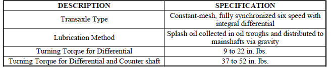
GENERAL SPECIFICATIONS
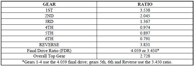
GEAR RATIOS
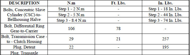
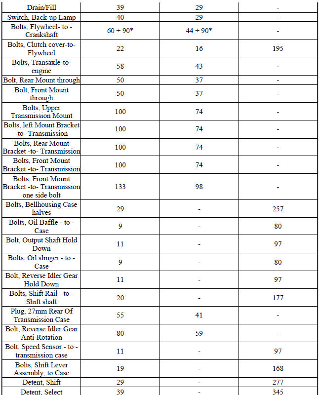
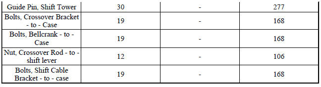
TORQUE SPECIFICATIONS
SPECIAL TOOLS
Fig. 145: Universal Handle C-4171

Fig. 146: Seal Installer 6709
Fig. 147: Remover, 9664
Fig. 148: Installer L-4520
Fig. 149: Installer 9935
Fig. 150: Installer 9928

Fig. 151: Puller 7794-A

Fig. 152: C-4657 Seal Installer
Fig. 153: Installer 9589

Fig. 154: Installer D-111

Fig. 155: Installer, Cup - D-144
Fig. 156: Bearing Splitter, P-334
Fig. 157: Fixture, 8925
Fig. 158: Puller 9647
Fig. 159: Sleeve C-3717
Fig. 160: Torque Tool C-4995
 Assembly
Fig. 65: Remove Input Shaft Bearing Cup
NOTE: Always use ATF on all moving parts during this assembly
procedure.
1. Use Bearing Cup Remover 9664 (2) and appropriate Slide Hammer (1) to
r ...
 Cable, gearshift control
REMOVAL
Fig. 161: Shift Cables & Bracket
1. Remove the shifter.
2. Raise hood.
3. Remove the resonator.
4. Remove engine cover.
5. Remove air cleaner assembly.
6. Disconnect ne ...
See also:
Geartrain, planetary
DESCRIPTION
Fig. 355: Identifying Planetary Geartrain Components
- FRONT SUN GEAR ASSEMBLY
- #6 THRUST BEARING
- #7 THRUST BEARING
- REAR CARRIER/FRONT ANNULUS ASSEMBLY
- REAR SUN GEAR
...
Removal
Fig. 93: Accessory Drive Belt System - 2.7L
- GENERATOR
- IDLER/TENSIONER
1. Perform fuel pressure release procedure before attempting any repairs.
2. Disconnect negative cable from rem ...
Tube, exhaust gas recirculation (EGR)
Removal
2.7L - LOWER TUBE
Fig. 50: Lower Exhaust Gas Recirculation Tube - 2.7L
WARNING: The normal operating temperature of the exhaust gas
recirculate (EGR)
valve and tube is very ...
