Dodge Journey: Operation
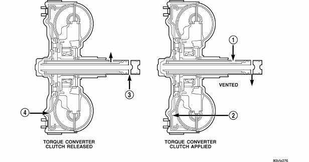
Fig. 427: Identifying Torque Converter Fluid Pressure Operation
- - APPLY PRESSURE
- - THE PISTON MOVES SLIGHTLY FORWARD
- - RELEASE PRESSURE
- - THE PISTON MOVES SLIGHTLY REARWARD
The converter impeller (driving member), which is integral to the converter housing and bolted to the engine drive plate, rotates at engine speed. The converter turbine (driven member), which reacts from fluid pressure generated by the impeller, rotates and turns the transmission input shaft .
TURBINE
As the fluid that was put into motion by the impeller blades strikes the blades of the turbine, some of the energy and rotational force is transferred into the turbine and the input shaft. This causes both of them (turbine and input shaft) to rotate in a clockwise direction following the impeller. As the fluid is leaving the trailing edges of the turbine's blades, it continues in a "hindering" direction back toward the impeller. If the fluid is not redirected before it strikes the impeller, it will strike the impeller in such a direction that it would tend to slow it down.
STATOR
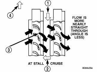
Fig. 428: Identifying Stator Operation
- - DIRECTION STATOR WILL FREE WHEEL DUE TO OIL PUSHING ON BACKSIDE OF VANES
- - FRONT OF ENGINE
- - INCREASED ANGLE AS OIL STRIKES VANES
- - DIRECTION STATOR IS LOCKED UP DUE TO OIL PUSHING AGAINST STATOR VANES
Torque multiplication is achieved by locking the stator's over-running clutch to its shaft. Under stall conditions (the turbine is stationary), the oil leaving the turbine blades strikes the face of the stator blades and tries to rotate them in a counterclockwise direction. When this happens the over-running clutch of the stator locks and holds the stator from rotating. With the stator locked, the oil strikes the stator blades and is redirected into a "helping" direction before it enters the impeller. This circulation of oil from impeller to turbine, turbine to stator, and stator to impeller, can produce a maximum torque multiplication of about 2.4:1. As the turbine begins to match the speed of the impeller, the fluid that was hitting the stator in such as way as to cause it to lock-up is no longer doing so. In this condition of operation, the stator begins to free wheel and the converter acts as a fluid coupling .
TORQUE CONVERTER CLUTCH (TCC)
In a standard torque converter, the impeller and turbine are rotating at about the same speed and the stator is freewheeling, providing no torque multiplication. By applying the turbine's piston to the front cover's friction material, a total converter engagement can be obtained. The result of this engagement is a direct 1:1 mechanical link between the engine and the transmission.
The engagement and disengagement of the TCC are automatic and controlled by the Powertrain Control Module (PCM). The engagement cannot be activated in the lower gears because it eliminates the torque multiplication effect of the torque converter necessary for acceleration. Inputs that determine clutch engagement are: coolant temperature, vehicle speed and throttle position. The torque converter clutch is engaged by the clutch solenoid on the valve body. The clutch will engage at approximately 56 km/h (35 mph) with light throttle, after the shift to third gear.
 Description
Fig. 422: Identifying Torque Converter Components
- TURBINE
- IMPELLER
- HUB
- STATOR
- CONVERTER CLUTCH DISC
- DRIVE PLATE
The torque converter is a hydraulic device that couples t ...
 Removal, Installation
REMOVAL
1. Remove transmission and torque converter from vehicle.
2. Place a suitable drain pan under the converter housing end of the
transmission.
CAUTION: Verify that transmission is ...
See also:
Description
Vehicle wheel alignment is the positioning of all interrelated front and rear
suspension angles. These angles
affect the handling and steering of the vehicle when it is in motion. Proper
wheel al ...
Core, service port valve
DESCRIPTION
Refrigerant system service ports are used to recover, recycle, evacuate,
charge and test the A/C refrigerant
system. Unique sizes are used on the two service ports for the R-134a
ref ...
Switch, remote radio
DESCRIPTION
Remote radio control switches are rocker-type switch units are mounted in the
upper spoke covers of the rear
(instrument panel side) steering wheel trim cover. The switch unit on the l ...
