Dodge Journey: Description, Operation
DESCRIPTION

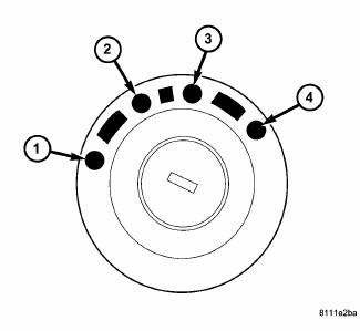
Fig. 418: Identifying Ignition Key/Switch Positions
- - LOCK
- - ACC
- - ON
- - START
The Brake Transmission Shifter/Ignition Interlock (BTSI) is a solenoid operated system that prevents the transmission gear shifter from being moved out of PARK without a driver in place.
OPERATION

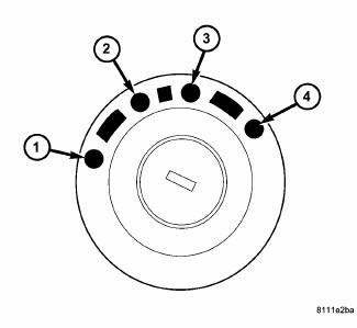
Fig. 419: Identifying Ignition Key/Switch Positions
- - LOCK
- - ACC
- - ON
- - START
The Brake Transmission Shifter/Ignition Interlock (BTSI) is engaged whenever the ignition switch is in the LOCK or ACC position. An additional electrically activated feature will prevent shifting out of the PARK position unless the brake pedal is depressed at least one-half inch. When the key is in the ON position and the brake pedal is depressed, the shifter is unlocked and will move into any position.

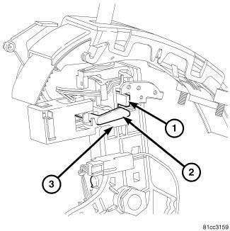
Fig. 420: Identifying Rotating Arm, Blocking Arm, & Shifter Gate Pin
When service brake pedal is not depressed the solenoid rotating arm (2) is free to rotate. The shifter gate pin (1) hits the blocking arm (3) and is prevented from moving from park.
When service brake is applied the rotating arm (2) is prevented from rotating by magnetic force within the solenoid. The shifter gate pin (1) pushes the rotating arm (2) and blocker arm (3) allowing the shifter to move out of park.
 Diagnosis and testing
SHIFT INTERLOCK SYSTEM
Fig. 421: Identifying Ignition Key/Switch Positions
- LOCK
- ACC
- ON
- START
The Shifter Response Table describes the normal operation of the
Brak ...
See also:
Installation
LEFT-HAND-DRIVE
NOTE: The master cylinder must be bled before installing it on the
vehicle.
1. Bench bleed the master cylinder.
2. Wipe the face of the power brake booster clean where the ...
PUBLICATION ORDER FORMS
To order the following manuals, you may use either the
website or the phone numbers listed below. Visa, Mastercard,
American Express, and Discover orders are accepted.
If you prefer mailing your pa ...
Ensioner, belt
Removal
2.4L ENGINE
Fig. 36: ACCESSORY DRIVE BELT - WORLD ENGINE
- POWER STEERING PUMP
- ACCESSORY DRIVE BELT
- GENERATOR
- CRANKSHAFT PULLEY
- LOWER IDLER PULLEY
- CRANKSHAFT PULLEY ...

