Dodge Journey: Installation
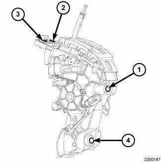
Fig. 404: Identifying Shifter Mounting Bolts
1. Install the shifter mounting bolts and tighten to 20 N.m (15 ft. lbs.) in the proper sequence as indicated on drawing.

Fig. 405: Identifying Shift Cable At Shifter
NOTE: Ensure the lock tab is in the lock position after the cable is installed onto the shifter housing (2).
2. Install the shift cable (1, 2) at the shifter.
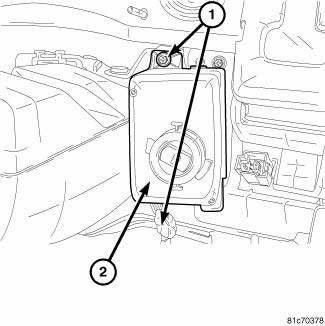
Fig. 406: Removing/Installing Screws At Win
3. Install the WIN (2) and install the mounting screws (1).
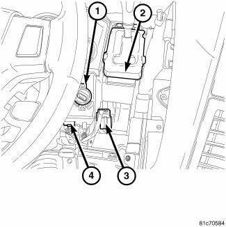
Fig. 407: Identifying Electrical Connectors At WIN & Shifter
4. Connect the electrical connectors (3, 4) at the WIN (1) and the shifter (2).
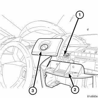
Fig. 408: Removing/Installing I/P Cover
5. Install the I/P cover (3).

Fig. 409: Identifying Knee Blocker
6. Install the knee blocker (2).
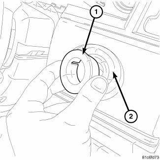
Fig. 410: Removing/Installing Ignition Switch Bezel
7. Install the shift knob.
8. Install the ignition switch bezel (1) to I/P cover (2).
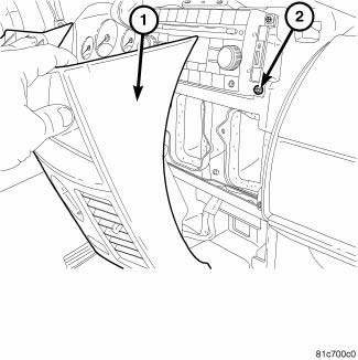
Fig. 411: Pulling Center Stack Back
9. Install center stack cover (1) back into position.
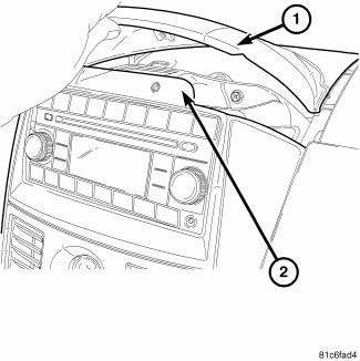
Fig. 412: Removing/Installing Center Stack Cover
10. Install the center stack top cover (1) back.
11. Install the cluster bezel.
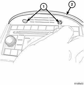
Fig. 413: Removing/Installing Screws At Center Stack Cover
12. Install the screws (1) at the center stack cover (2).
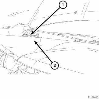
Fig. 414: Removing/Installing Defroster Cover
13. Install the defroster cover (1).
14. Connect the battery cable.
 Removal
Fig. 393: Removing/Installing Defroster Cover
1. Disconnect the negative battery cable.
2. Using a trim stick remove the defroster cover (1).
Fig. 394: Removing/Installing Screws At Center St ...
 Solenoid, pressure control
DESCRIPTION
Fig. 415: Identifying Variable Line Pressure Components
- PRESSURE CONTROL SOLENOID
- LINE PRESSURE SENSOR
- SHOULDER SCREW
- VARIABLE LINE PRESSURE HEADER
- MANUAL SHAFT
...
See also:
Reservoir, brake master cylinder
Removal
CAUTION: If at any time the master cylinder is loosened or
removed, you must
perform the master cylinder installation procedure to ensure that the
seal
(o-ring) is still ...
Installation
Fig. 101: Check For Stretched Bolts
- STRETCHED BOLT
- THREADS ARE NOT STRAIGHT ON LINE
- THREADS ARE STRAIGHT ON LINE
- UNSTRETCHED BOLT
NOTE: The cylinder head bolts (4) are tighte ...
INSTRUMENT CLUSTER DESCRIPTIONS
1. Coolant Temperature Gauge
The temperature gauge indicates engine coolant temperature.
Any reading within the normal range indicates
that the cooling system is operating satisfactorily. The
gaug ...
