Dodge Journey: Sensor, speed, input
DESCRIPTION
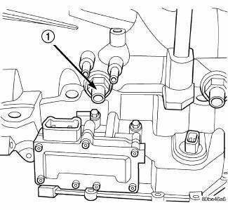
Fig. 369: Removing/Installing Input Speed Sensor
- - INPUT SPEED SENSOR
The Input Speed Sensor (1) , is a two-wire magnetic pickup device that generates AC signals as rotation occurs.
It is threaded into the transaxle case.
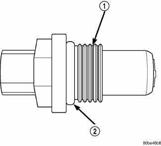
Fig. 370: Identifying Input Speed Sensor & O-Ring
- - INPUT SPEED SENSOR
- - O-RING
The Input Speed Sensor (1) is sealed with an O-ring (2) , and is considered a primary input to the Powertrain/Transmission Control Module.
OPERATION
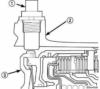
Fig. 371: Identifying Input Speed Sensor & Input Clutch Hub
- - INPUT SPEED SENSOR
- - TRANSAXLE CASE
- - INPUT CLUTCH HUB
The Input Speed Sensor (1) provides information on how fast the input shaft is rotating. As the teeth of the input clutch hub (3) pass by the sensor coil, an AC voltage is generated and sent to the PCM/TCM. The PCM/TCM interprets this information as input shaft RPM.
The PCM/TCM compares the input speed signal with output speed signal to determine the following:
- Transmission gear ratio
- Speed ratio error detection
- CVI calculation
The PCM/TCM also compares the input speed signal and the engine speed signal to determine the following:
- Torque converter clutch slippage
- Torque converter element speed ratio
REMOVAL
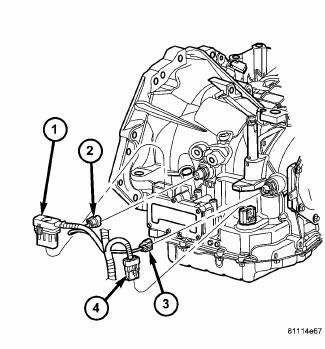
Fig. 372: Identifying Transmission Connectors
- - SOLENOID PACK CONNECTOR
- - INPUT SPEED SENSOR CONNECTOR
- - OUTPUT SPEED SENSOR CONNECTOR
- - TRANSMISSION RANGE SENSOR CONNECTOR
1. Disconnect battery negative cable.
2. Disconnect input speed sensor connector (2) .
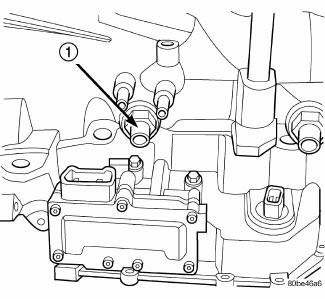
Fig. 373: Removing/Installing Input Speed Sensor
- - INPUT SPEED SENSOR
3. Unscrew and remove input speed sensor (1) .
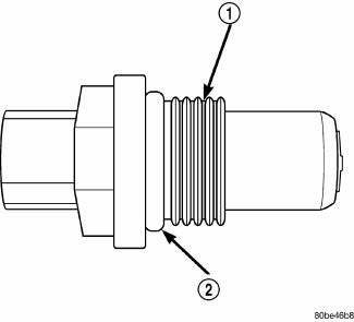
Fig. 374: Identifying Input Speed Sensor & O-Ring
- - INPUT SPEED SENSOR
- - O-RING
4. Inspect speed sensor O-ring (2) and replace if necessary.
INSTALLATION
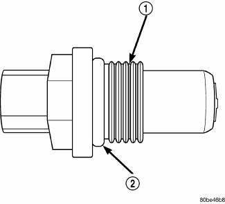
Fig. 375: Identifying Input Speed Sensor & O-Ring
- - INPUT SPEED SENSOR
- - O-RING
1. Verify O-ring (2) is installed into position.
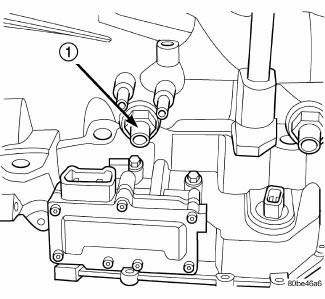
Fig. 376: Removing/Installing Input Speed Sensor
- - INPUT SPEED SENSOR
2. Install and tighten input speed sensor (1) to 27 N.m (20 ft. lbs.).
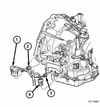
Fig. 377: Identifying Transmission Connectors
- - SOLENOID PACK CONNECTOR
- - INPUT SPEED SENSOR CONNECTOR
- - OUTPUT SPEED SENSOR CONNECTOR
- - TRANSMISSION RANGE SENSOR CONNECTOR
3. Connect speed sensor connector (4) .
4. Connect battery negative cable.
 Seal, oil pump
REMOVAL
Fig. 367: Removing Oil Pump Seal
- SEAL PULLER C-3981-B
- OIL PUMP SEAL
1. Remove transaxle from vehicle.
2. Using Seal Puller C-3981B (1) , remove oil pump seal (2).
INSTALLA ...
 Sensor, speed, output
DESCRIPTION
Fig. 378: Identifying Output Speed Sensor
- OUTPUT SPEED SENSOR
The Output Speed Sensor (1) is a two-wire magnetic pickup device that
generates an AC signal as rotation
occurs ...
See also:
Description
Four-wheel disc brakes are standard on this vehicle. Each disc brake assembly
consists of the following major
components:
Caliper
Caliper adapter bracket
Pads (Shoe and lining assemblies)
...
Without intermediate shaft
NOTE: The inner tripod joints are designed with a retention feature
that prevents the
tripod rollers from coming out of the inner joint housing up to a specific
load. If
this feature is o ...
EMISSIONS INSPECTION AND MAINTENANCE PROGRAMS
In some localities, it may be a
legal requirement to pass
an inspection of this vehicle’s emissions control system.
Failure to pass could prevent vehicle registration.
For states that require a ...
