Dodge Journey: Relay, transmission control
DESCRIPTION

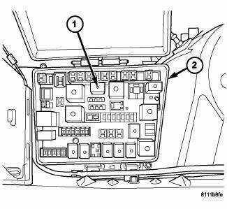
Fig. 366: Locating Transmission Control Relay
- - TRANSMISSION CONTROL RELAY
- - POWER DISTRIBUTION CENTER
The transmission control relay (1) is located in the Power Distribution Center (PDC) (2), which is located on the left side of the engine compartment between the battery and radiator upper support.
OPERATION
The Transmission Control Relay is supplied fused B+ voltage, energized by the PCM, and is used to supply power to the solenoid pack when the transmission is in normal operating mode. When the relay is "off", no power is supplied to the solenoid pack and the transmission is in "limp-in" mode. After a controller reset (ignition key turned to the "run" position or after cranking engine), the PCM energizes the relay. Prior to this, the PCM verifies that the contacts are open by checking for no voltage at the switched battery terminals. After this is verified, the voltage at the solenoid pack pressure switches is checked. After the relay is energized, the PCM monitors the terminals to verify that the voltage is greater than 3 volts.
 Pump, transmission oil
DESCRIPTION
Fig. 359: Identifying Transmission Oil Pump Assembly
- PUMP HOUSING
- OUTER PUMP GEAR
- INNER PUMP GEAR
- REACTION SHAFT SUPPORT
- SEAL RINGS (4)
- REACTION SHAFT
- CRES ...
 Seal, oil pump
REMOVAL
Fig. 367: Removing Oil Pump Seal
- SEAL PULLER C-3981-B
- OIL PUMP SEAL
1. Remove transaxle from vehicle.
2. Using Seal Puller C-3981B (1) , remove oil pump seal (2).
INSTALLA ...
See also:
Switch, backup lamp
DESCRIPTION
Fig. 43: Backup Lamp Switch
Vehicles equipped with a manual transmission (2) have a normally open,
spring-loaded plunger type backup
lamp switch (1). Vehicles with an optional elect ...
Removal
BEVERAGE COOLER
WARNING: Disable the airbag system before attempting any steering
wheel, steering
column, or instrument panel component diagnosis or service. Disconnect
and isolate t ...
Geartrain, planetary
DESCRIPTION
Fig. 355: Identifying Planetary Geartrain Components
- FRONT SUN GEAR ASSEMBLY
- #6 THRUST BEARING
- #7 THRUST BEARING
- REAR CARRIER/FRONT ANNULUS ASSEMBLY
- REAR SUN GEAR
...
