Dodge Journey: Holding clutches
DESCRIPTION

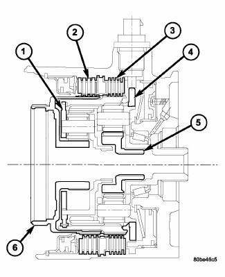
Fig. 356: Identifying 2/4 & Low/Reverse Clutches & Planetary Geartrain
Components
- - FRONT PLANET CARRIER/REAR ANNULUS
- - 2/4 CLUTCH
- - L/R CLUTCH
- - REAR PLANET CARRIER/FRONT ANNULUS
- - REAR SUN GEAR
- - FRONT SUN GEAR ASSEMBLY
Two hydraulically applied multi-disc clutches are used to hold planetary geartrain components (1,4) stationary while the input clutches drive others. The 2/4 (2) and Low/Reverse (3) clutches are considered holding clutches and are contained at the rear of the transaxle case.
OPERATION
NOTE: Refer to ELEMENTS IN USE AT EACH POSITION OF SELECTOR LEVER for a collective view of which clutch elements are applied at each position of the selector lever.
2/4 CLUTCH
The 2/4 clutch is hydraulically applied in Second and Fourth gears by pressurized fluid against the 2/4 clutch piston. When the 2/4 clutch is applied, the front sun gear assembly is held or grounded to the transaxle case.
LOW/REVERSE CLUTCH
The Low/Reverse clutch is hydraulically applied in Park, Reverse, Neutral, and First gears by pressurized fluid against the Low/Reverse clutch piston. When the Low/Reverse clutch is applied, the front planet carrier/rear annulus assembly is held or grounded to the transaxle case.
 Geartrain, planetary
DESCRIPTION
Fig. 355: Identifying Planetary Geartrain Components
- FRONT SUN GEAR ASSEMBLY
- #6 THRUST BEARING
- #7 THRUST BEARING
- REAR CARRIER/FRONT ANNULUS ASSEMBLY
- REAR SUN GEAR
...
 Knob, gearshift
REMOVAL
Fig. 357: Removing/Installing Gearshift Knob
1. Loosen the set screw (3) on the shift knob (2).
2. Hold in the shift knob button (1).
3. Pull up on the shift knob (2) while holding t ...
See also:
Description, Operation, Specifications
DESCRIPTION
NOTE: All engines use a fixed ignition timing system. Basic ignition
timing is not
adjustable. All spark advance is determined by the Powertrain Control Module
(PCM).
The ign ...
Relay, heater unit
DESCRIPTION
Fig. 320: Standard ISO-Type Relay
Three relays (1) are used for the electric positive temperature coefficient (PTC)
heater system when equipped
with the 2.0L diesel engine. The rela ...
Description, Diagnosis and Testing
Description
Fig. 17: PEDAL AND BOOSTER MOUNTING - LHD
The power brake booster (3) is mounted to the engine side of the dash panel.
The master cylinder is bolted to
the front of the booster. A v ...
