Dodge Journey: Disassembly
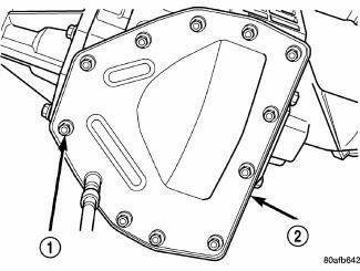
Fig. 314: Removing/Installing Differential Cover Bolts
- - DIFFERENTIAL COVER BOLTS
- - DIFFERENTIAL COVER
NOTE: The transfer shaft should be removed for differential repair and bearing turning torque checking
1. Remove the differential cover bolts (1).
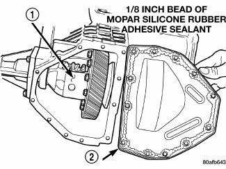
Fig. 315: Identifying Differential Cover
- - DIFFERENTIAL ASSEMBLY
- - DIFFERENTIAL COVER
2. Remove the differential cover (2).
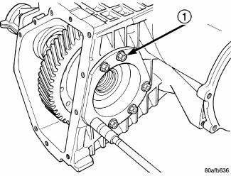
Fig. 316: Removing/Installing Differential Bearing Retainer Bolts
- - DIFFERENTIAL RETAINER BOLTS
3. Remove the differential bearing retainer bolts (1).
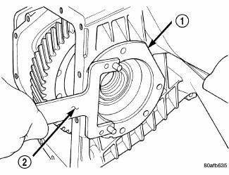
Fig. 317: Removing Differential Bearing Retainer
- - DIFFERENTIAL BEARING RETAINER
- - BEARING PULLER L-4435
4. Remove the differential bearing retainer (1).
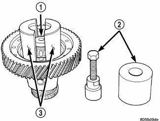
Fig. 318: Removing Differential Bearing Cone On Extension Housing Side
- - THRUST BUTTON L-4539-2
- - PULLER SET 5048
- - COLLETS 5048-4
5. Using a plastic hammer, remove extension housing/adapter plate on the right side of the transaxle.
WARNING: Hold onto differential assembly to prevent it from rolling out of housing.
6. Use Puller Set 5048 (2), 5048-3 Collets (3), and L-4539-2 Button (1) to remove the differential bearing cone on the extension housing side.
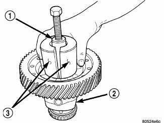
Fig. 319: Installing Puller Set 5048, 5048-4 Collets, & L-4539-2 Button To
Differential Bearing
Cone On Bearing Retainer Side
- - PULLER SET 5048
- - DIFFERENTIAL
- - COLLETS 5048-4
7. Install Puller Set 5048 (1), 5048-4 Collets (3), and L-4539-2 Button to the differential bearing cone on the bearing retainer side.
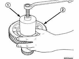
Fig. 320: Removing Differential Bearing Cone On Bearing Retainer Side
- - PULLER SET 5048
- - RING GEAR
8. Remove the differential bearing cone on the bearing retainer side.
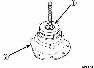
Fig. 321: Installing Special Jaw Set L-4518 & Remover 6062A Onto Differential
Bearing Race
- - REMOVER 6062A
- - DIFFERENTIAL BEARING RETAINER
9. Install Special Jaw Set L-4518 and Remover 6062A (1), onto the differential bearing race from the extension housing.
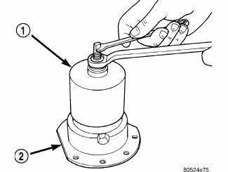
Fig. 322: Removing Differential Bearing Race From Bearing Retainer
- - REMOVER 6062A
- - DIFFERENTIAL BEARING RETAINER
10. Remove the differential bearing race from the bearing retainer (2).
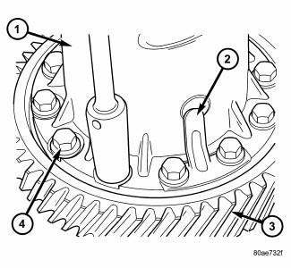
Fig. 323: Identifying Ring Gear-To-Differential Case Bolts & Floating Pinion
Shaft Retainers
- - DIFFERENTIAL CASE
- - PINION SHAFT RETAINER
- - RING GEAR
- - RING GEAR-TO-CASE BOLT
11. Remove ring gear-to-differential case bolts (4) and floating pinion shaft retainers (2).
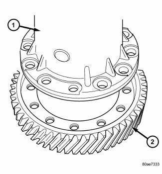
Fig. 324: Identifying Ring Gear & Differential Case
- - DIFFERENTIAL CASE
- - RING GEAR
12. Separate ring gear (2) from differential case (1).
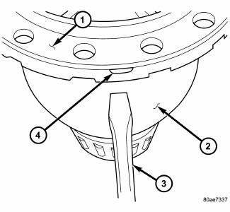
Fig. 325: Identifying Differential Cover At Case
- - DIFFERENTIAL SUPPORT
- - DIFFERENTIAL CASE
- - SCREWDRIVER
- - RELIEF (2 @ 180º APART)
13. Separate differential cover (1) from case (2) using suitable screwdrivers at position.
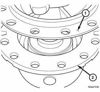
Fig. 326: Identifying Differential Support
- - DIFFERENTIAL SUPPORT
- - DIFFERENTIAL CASE
14. Lift support (1) from case (2) .
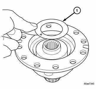
Fig. 327: Removing/Installing Side Gear Thrust Washer
- - SIDE GEAR THRUST WASHER
15. Remove side gear thrust washer (1) .
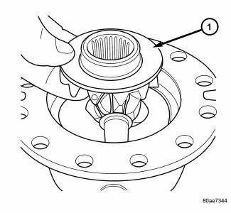
Fig. 328: Removing/Installing Side Gear
- - DIFFERENTIAL SIDE GEAR
16. Remove side gear (1) .
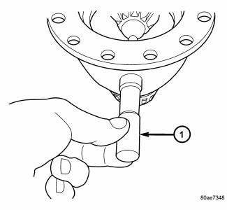
Fig. 329: Removing/Installing Pinion Shaft
- - PINION SHAFT
17. Remove pinion shaft (1) .
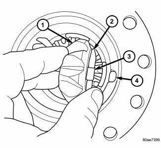
Fig. 330: Removing/Installing Pinion Gears & Tabbed Washers
- - PINION GEAR
- - TABBED WASHER
- - LOCATING TAB
- - NOTCH
18. Remove pinion gears (1) and tabbed washers (2) .
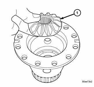
Fig. 331: Removing/Installing Differential Side Gear
- - DIFFERENTIAL SIDE GEAR
19. Remove differential side gear (1) .
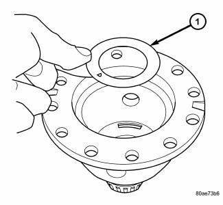
Fig. 332: Removing/Installing Side Gear Thrust Washer
- - THRUST WASHER
20. Remove side gear thrust washer (1) .
21. Inspect all components for excessive wear.
 Description, Operation
DESCRIPTION
Fig. 313: Identifying Differential Assembly
- DIFFERENTIAL CASE
- RING GEAR
- TRANSFER SHAFT
- PINION GEAR
- PINION SHAFT
- SIDE GEAR
The 41TE differential is a convent ...
 Assembly
Fig. 333: Identifying Thrust Washer
- THRUST WASHER
NOTE: The differential is serviced as an assembly. Differential
service is limited to
bearing cups and cones. Any other differentia ...
See also:
Diagnosis and Testing
BRAKE LAMP SWITCH
WARNING: To avoid serious or fatal injury on vehicles equipped
with airbags, disable
the Supplemental Restraint System (SRS) before attempting any steering
wheel, s ...
FLUID CAPACITIES
FLUID CAPACITIES ...
Removal
2.4L
Fig. 11: Identifying Ignition Coil Electrical Connectors
NOTE: Prior to removing coil, spray compressed air around coil top to
make sure no
dirt drops into the spark plug tube.
The ...
