Dodge Journey: Removal, Installation
REMOVAL
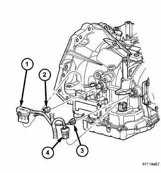
Fig. 298: Identifying Transmission Connectors
- - SOLENOID PACK CONNECTOR
- - INPUT SPEED SENSOR CONNECTOR
- - OUTPUT SPEED SENSOR CONNECTOR
- - TRANSMISSION RANGE SENSOR CONNECTOR
NOTE: If solenoid/pressure switch assembly is being replaced, the "Quick-Learn" procedure must be performed.
1. Disconnect battery negative cable.
2. Remove air cleaner assembly.
3. Disconnect solenoid/pressure switch assembly connector (1) .
4. Disconnect input speed sensor connector (2).
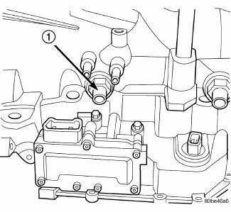
Fig. 299: Removing/Installing Input Speed Sensor
- - INPUT SPEED SENSOR
5. Remove input speed sensor (1) .
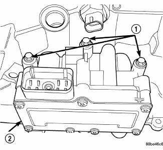
Fig. 300: Removing/Installing Solenoid/Pressure Switch Assembly-To-Transaxle
Case Bolts
- - BOLTS
- - SOLENOID AND PRESSURE SWITCH ASSEMBLY
6. Remove three solenoid/pressure switch assembly-to-transaxle case bolts (1) .
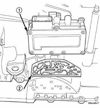
Fig. 301: Removing/Installing Solenoid/Pressure Switch Assembly & Gasket
- - SOLENOID/PRESSURE SWITCH ASSEMBLY
- - GASKET
7. Remove solenoid/pressure switch assembly (1) and gasket (2). Use care to prevent gasket material and foreign objects from become lodged in the transaxle case ports.
INSTALLATION
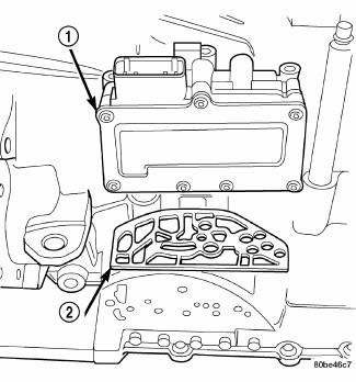
Fig. 302: Removing/Installing Solenoid/Pressure Switch Assembly & Gasket
- - SOLENOID/PRESSURE SWITCH ASSEMBLY
- - GASKET
NOTE: If solenoid/pressure switch assembly is being replaced, it is necessary to perform the "Quick-Learn" procedure.
1. Install solenoid/pressure switch assembly and new gasket to transaxle .
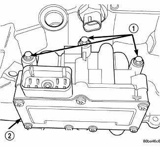
Fig. 303: Removing/Installing Solenoid/Pressure Switch Assembly-To-Transaxle
Case Bolts
- - BOLTS
- - SOLENOID AND PRESSURE SWITCH ASSEMBLY
2. Install and torque three bolts (1) to 12 N.m (105 in. lbs.).
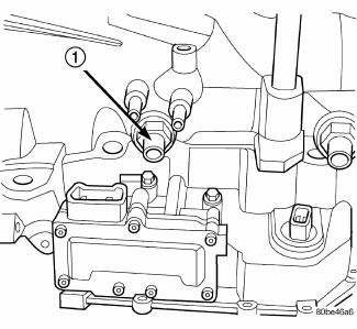
Fig. 304: Removing/Installing Input Speed Sensor
- - INPUT SPEED SENSOR
3. Install input speed sensor (1) and torque to 27 N.m (20 ft. lbs.).
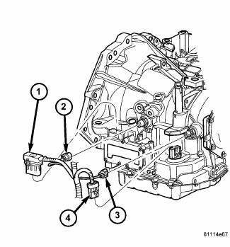
Fig. 305: Identifying Transmission Connectors
- - SOLENOID PACK CONNECTOR
- - INPUT SPEED SENSOR CONNECTOR
- - OUTPUT SPEED SENSOR CONNECTOR
- - TRANSMISSION RANGE SENSOR CONNECTOR
4. Connect input speed sensor connector (2) .
5. Install solenoid/pressure switch 8-way connector and torque to 4 N.m (35 in. lbs.).
6. Install air cleaner assembly.
7. Connect battery negative cable.
8. If solenoid/pressure switch assembly was replaced, perform the "Quick-Learn" procedure.
 Description, Operation
DESCRIPTION
Fig. 297: Identifying Solenoid/Pressure Switch Assembly
- SOLENOID AND PRESSURE SWITCH ASSEMBLY
The Solenoid/Pressure Switch Assembly (1) is external to the transaxle and
mount ...
 Cable, shift
REMOVAL
Fig. 306: Identifying Knee Blocker
1. Remove the knee blocker (2).
Fig. 307: Identifying Shift Cable At Shifter
NOTE: Ensure the lock tab on the shift cable (2) is depressed before ...
See also:
Operation
SYSTEM
The Powertrain Control Module (PCM) monitors many different circuits in the
fuel injection, ignition, emission
and engine systems. If the PCM senses a problem with a monitored circuit often ...
Removal
WARNING: Refer to the applicable warnings and cautions for this
system before
performing the following operation. Failure to follow these instructions
may
result in serious or fat ...
Cylinder compression pressure test
The results of a cylinder compression pressure test can be utilized to
diagnose several engine malfunctions.
Ensure the battery is completely charged and the engine starter motor is in
good opera ...
