Dodge Journey: Description, Operation
DESCRIPTION
Fig. 297: Identifying Solenoid/Pressure Switch Assembly
- - SOLENOID AND PRESSURE SWITCH ASSEMBLY
The Solenoid/Pressure Switch Assembly (1) is external to the transaxle and mounted to the transaxle case. The assembly consists of four solenoids that control hydraulic pressure to the LR/CC, 2/4, OD, and UD friction elements. The reverse clutch is controlled by line pressure from the manual valve in the valve body. The solenoids are contained within the Solenoid/Pressure Switch Assembly, and can only be serviced by replacing the assembly.
The solenoid assembly also contains pressure switches that monitor and send hydraulic circuit information to the PCM/TCM. Likewise, the pressure switches can only be service by replacing the assembly.
OPERATION
SOLENOIDS
The solenoids receive electrical power from the Transmission Control Relay through a single wire. The PCM/TCM energizes or operates the solenoids individually by grounding the return wire of the solenoid needed. When a solenoid is energized, the solenoid valve shifts, and a fluid passage is opened or closed (vented or applied), depending on its default operating state. The result is an apply or release of a frictional element.
The 2/4 and UD solenoids are normally applied, which by design allow fluid to pass through in their relaxed or "off" state. This allows transaxle limp-in (P,R,N,2) in the event of an electrical failure.
The continuity of the solenoids and circuits are periodically tested. Each solenoid is turned on or off depending on its current state. An inductive spike should be detected by the PCM/TCM during this test. It no spike is detected, the circuit is tested again to verify the failure. In addition to the periodic testing, the solenoid circuits are tested if a speed ratio or pressure switch error occurs.
PRESSURE SWITCHES
The PCM/TCM relies on three pressure switches to monitor fluid pressure in the L/R, 2/4, and OD hydraulic circuits. The primary purpose of these switches is to help the PCM/TCM detect when clutch circuit hydraulic failures occur. The range for the pressure switch closing and opening points is 11-23 psi. Typically the switch opening point will be approximately one psi lower than the closing point. For example, a switch may close at 18 psi and open at 17 psi. The switches are continuously monitored by the PCM/TCM for the correct states (open or closed) in each gear as shown in the following chart:
PRESSURE SWITCH STATES
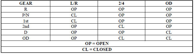
A Diagnostic Trouble Code (DTC) will set if the PCM/TCM senses any switch open or closed at the wrong time in a given gear.
The PCM/TCM also tests the 2/4 and OD pressure switches when they are normally off (OD and 2/4 are tested in 1st gear, OD in 2nd gear, and 2/4 in 3rd gear). The test simply verifies that they are operational, by looking for a closed state when the corresponding element is applied. Immediately after a shift into 1st, 2nd, or 3rd gear with the engine speed above 1000 RPM, the PCM/TCM momentarily turns on element pressure to the 2/4 and/or OD clutch circuits to identify that the appropriate switch has closed. If it doesn't close, it is tested again.
If the switch fails to close the second time, the appropriate Diagnostic Trouble Code (DTC) will set.

 Removal, Installation
REMOVAL
Fig. 298: Identifying Transmission Connectors
- SOLENOID PACK CONNECTOR
- INPUT SPEED SENSOR CONNECTOR
- OUTPUT SPEED SENSOR CONNECTOR
- TRANSMISSION RANGE SENSOR CONNECTOR
...
See also:
Body, air cleaner
REMOVAL
1. Disconnect negative battery cable.
Fig. 87: Inlet Air Temperature Sensor Electrical Connector
2. Disconnect inlet air temperature sensor electrical connector (3).
3. Disconnect fres ...
Filter, particulate air
Description
Fig. 85: Filter-Particulate Air Description
Some models are equipped with a particulate air filter (1) that helps purify
the outside air entering the HVAC
housing. The filter is mou ...
Removal
2.0L TURBO DIESEL
Fig. 2: Generator Cables
1. Remove engine cover.
2. Disconnect and isolate the negative battery cable.
3. Remove accessory drive belt.
4. Disconnect battery cable fro ...
