Dodge Journey: Assembly
Fig. 257: Installing Input Shaft
- - INPUT SHAFT
- - ARBOR PRESS
- - INPUT SHAFT HUB ASSEMBLY
Use petrolatum on all seals to ease assembly of components.
1. Using an arbor press (2), install input shaft (1) to input shaft hub (3) .
Fig. 258: Installing Input Shaft Snap Ring
- - INPUT SHAFT
- - SCREWDRIVER (DO NOT SCRATCH BEARING SURFACE)
- - SNAP RING
- - O-RINGS
- - SEALS
2. Install input shaft snap ring (3) .
Fig. 259: Identifying OD/Reverse Piston, Return Spring, & Snap Ring
- - OD/REVERSE PISTON
- - RETURN SPRING
- - SNAP RING
- - O-RING
3. Place OD/Reverse piston (1) return spring (2) and snap ring (3) into position.
Fig. 260: Installing OD/Reverse Piston, Return Spring, & Snap Ring
- - ARBOR PRESS RAM (COMPRESS RETURN SPRING JUST ENOUGH TO REMOVE OR INSTALL SNAP RING)
- - SCREWDRIVER
- - SNAP RING
- - Disk 6057
- - OD/REVERSE PISTON
- - RETURN SPRING
4. Using an arbor press (1) and Disk 6057 (4), install OD/Reverse piston (5) return spring (6) and snap ring (3).
Fig. 261: Installing OD/Reverse Piston
- - PUSH DOWN TO INSTALL OVERDRIVE/REVERSE PISTON
- - INPUT CLUTCHES RETAINER
5. Install the OD/Reverse piston assembly (1) to the input clutch retainer (2)
Fig. 262: Installing Input Shaft Hub Assembly
- - PUSH DOWN TO INSTALL INPUT SHAFT HUB ASSEMBLY (ROTATE TO ALIGN SPLINES)
- - OD/REV. PISTON
6. Install the input hub/shaft assembly (rotate to align splines) (1) to the OD/Reverse piston/clutch retainer assembly (2)
Fig. 263: Identifying Input Clutch Hub, Retainer, & OD/Reverse Piston
- - SNAP RING (INPUT SHAFT)
- - SNAP RING
- - CLUTCH RETAINER
- - SEAL, OUTER
- - SEAL, INNER
- - OD/REVERSE PISTON
- - SEAL, INPUT SHAFT
- - SHAFT, INPUT
- - HUB
- - SEAL
- - SNAP RING
- - BELLEVILLE SPRING
7. Refer to Fig. 263 as necessary when performing the following steps .
Fig. 264: Installing Input Hub Tapered Snap Ring
- - INPUT SHAFT
- - INPUT HUB SNAP RING (TAPERED SIDE UP WITH TABS IN CAVITY)
- - SNAP RING PLIERS
8. Install input hub tapered snap ring (tapered side up with tabs in cavity) (2) .
Fig. 265: Installing Underdrive Clutch Piston
- - PISTON
9. Install UD clutch piston (1) .
Fig. 266: Installing UD Piston Return Spring & Installer 5067
- - PISTON RETURN SPRING
- - INSTALLER 5067
- - INPUT SHAFT CLUTCHES RETAINER ASSEMBLY
10. Install UD piston return spring (1) and Installer 5067 (2).
Fig. 267: Removing/Installing Underdrive Clutch Piston, Spring & Retainer
- - SNAP RING
- - SPRING RETAINER
- - SPRING
- - UD CLUTCH PISTON
- - SEAL, OUTER
- - SEAL, INNER
- - INPUT CLUTCH ASSEMBLY
11. Refer to Fig. 267 as necessary when performing the following steps.
Fig. 268: Identifying UD Spring Retainer & Snap Ring
- - UNDERDRIVE SPRING RETAINER
- - SNAP RING
- - SEAL
- - PISTON RETURN SPRING
12. Place the UD spring retainer (1) and snap ring (2) into position.
Fig. 269: Installing UD Spring Retainer and Snap Ring
- - ARBOR PRESS RAM
- - SNAP RING PLIERS
- - SNAP RING
- - OD/REVERSE PISTON
- - INSTALLER 5067
- - COMPRESSOR 5059-A
13. Using Compressor 5059-A (6) and an arbor press (1), Install the UD spring retainer and snap ring (3) Compress just enough to install snap ring (3)
CAUTION: Compress return spring just enough to install snap ring.
Fig. 270: Installing Underdrive UD Clutch Pack
- - CLUTCH PLATE
- - ONE UD CLUTCH DISC
- - CLUTCH DISC
14. Install the UD clutch pack (1,3) . Leave out upper disc (2), until snap ring is installed.
Fig. 271: Installing UD Clutch Flat Snap Ring
- - UNDERDRIVE CLUTCH REACTION PLATE FLAT SNAP RING
- - SCREWDRIVER
15. Install the UD clutch flat snap ring (1)
Fig. 272: Installing Last UD Clutch Disc
- - ONE UNDERDRIVE CLUTCH DISC
16. Install the last UD clutch disc (1) .
Fig. 273: Installing OD/UD Clutches Reaction Plate
- - OD/UD CLUTCH REACTION PLATE (TAPERED STEP SIDE UP)
17. Place the OD/UD clutch reaction plate (1) and snap ring into position. The OD/UD clutches reaction plate has a step on both sides. Install the OD/UD clutches reaction plate tapered step side up.
Fig. 274: Installing Snap Ring
- - OVERDRIVE/UNDERDRIVE CLUTCHES REACTION PLATE TAPERED SNAP RING
- - SCREWDRIVER (DO NOT SCRATCH REACTION PLATE)
18. Install the snap ring (1) using a screwdriver (2).
NOTE: Snap ring ends must be located within one finger of the input clutch hub.
Be sure that snap ring is fully seated, by pushing with screwdriver, into snap ring groove all the way around.

Fig. 275: Removing/Installing OD/UD Reaction Plate Tapered Snap Ring, Clutch
Plate, & First
Clutch Disc
- - SNAP RING (TAPERED)
- - OD/UD REACTION PLATE
- - CLUTCH DISC
- - SNAP RING (FLAT)
- - CLUTCH PLATE
- - INPUT CLUTCH ASSEMBLY
19. Refer to Fig. 275 as necessary when performing the following steps .
Fig. 276: Seating Tapered Snap Ring
- - OVERDRIVE/UNDERDRIVE CLUTCHES REACTION PLATE TAPERED SNAP RING
- - SCREWDRIVER
20. Seat tapered snap ring (1) to ensure proper installation.
Fig. 277: Installing Input Clutch Assembly
- - INPUT CLUTCH ASSEMBLY
- - INPUT CLUTCH PRESSURE FIXTURE 8391
21. Install input clutch assembly (1) to the Input Clutch Pressure Fixture 8391 (2) .
Fig. 278: Identifying Dial Indicator & UD Clutch Pack
- - DIAL INDICATOR
- - UNDERDRIVE CLUTCH
22. Set up dial indicator (1) on the UD clutch pack (2) .
Fig. 279: Measuring UD Clutch Pack Clearance
- - DIAL INDICATOR
- - UNDERDRIVE CLUTCH
23. Using moderate pressure, press down and hold (near indicator) the UD clutch pack (2) with screwdriver or suitable tool and zero dial indicator . When releasing pressure on clutch pack, indicator reading should advance 0.005-0.010.
CAUTION: Do not apply more than 30 psi (206 kPa) to the underdrive clutch pack.
24. Apply 30 psi (206 kPa) to the underdrive hose on Input Clutch Pressure Fixture 8391 and measure UD clutch clearance. Measure and record UD clutch pack measurement in four places, 90º apart.
25. Take average of four measurements and compare with UD clutch pack (2) clearance specification.
Underdrive clutch pack clearance must be 0.94-1.50 mm (0.037-0.059 in.).
26. If necessary, select the proper reaction plate to achieve specifications:
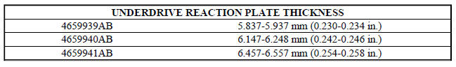
Fig. 280: Installing OD Clutch Pack
- - OVERDRIVE CLUTCH PACK
27. Install the OD clutch pack (four frictions/three steels) (1) .
Fig. 281: Installing Waved Snap Ring
- - OVERDRIVE PRESSURE PLATE WAVED SNAP RING
- - SCREWDRIVER
28. Install OD pressure plate waved snap ring (1) .
Fig. 282: Installing OD/Reverse Pressure Plate
- - OVERDRIVE/REVERSE PRESSURE PLATE
- - (STEP SIDE DOWN)
29. Install the OD/Reverse pressure plate (1) with large step down (towards OD clutch pack) (2) .
Fig. 283: Removing/Installing OD/Reverse Pressure Plate Snap Ring
- - SNAP RING
- - OD/REVERSE PRESSURE PLATE
- - SNAP RING (WAVE)
- - CLUTCH DISC (4)
- - CLUTCH STEEL (3)
- - INPUT CLUTCH ASSEMBLY
30. Refer to Fig. 283 as necessary when performing the following steps .
Fig. 284: Installing Flat Snap Ring
- - ARBOR PRESS RAM
- - COMPRESSOR 5059-A
- - FLAT SNAP RING
31. Install OD pressure plate flat snap ring (3) .
Fig. 285: Measuring OD Clutch Pack Clearance
- - DIAL INDICATOR
- - OD/REVERSE REACTION PLATE
32. Measure OD clutch pack clearance. Set up dial indicator (1) on top of the OD/Reverse pressure plate.
33. Zero dial indicator and apply 30 psi (206 kPa) air pressure to the overdrive clutch hose on Tool 8391.
Measure and record OD clutch pack measurement in four places, 90º apart.
34. Take average of four measurements and compare with OD clutch pack clearance specification. The overdrive (OD) clutch pack clearance is 1.07-3.25 mm (0.042-0.128 in.).
If not within specifications, the clutch is not assembled properly. There is no adjustment for the OD clutch clearance.
35. Install reverse clutch pack (two frictions/one steel) (1,2) .
Fig. 286: Installing Reverse Clutch Reaction Plate
- - REVERSE CLUTCH REACTION PLATE (FLAT SIDE DOWN)
36. Install reverse clutch reaction plate with the flat side down towards reverse clutch .
Fig. 287: Removing/Installing Reverse Clutch Pack
- - SNAP RING
- - REACTION PLATE
- - CLUTCH DISC (2)
- - CLUTCH PLATE (1)
- - INPUT CLUTCH ASSEMBLY
37. Refer to Fig. 287 as necessary when performing the following steps .
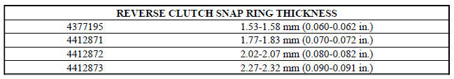
Fig. 288: Installing Reverse Clutch Snap Ring
- - REVERSE CLUTCH SNAP RING (SELECT)
- - SCREWDRIVER
- - REVERSE CLUTCH REACTION PLATE
38. Tap reaction plate (3) down to allow installation of the reverse clutch snap ring (1) Install reverse clutch snap ring (1).
Fig. 289: Prying Up Reaction Plate To Seat Against Snap Ring
- - SCREWDRIVER
- - SNAP RING
- - SCREWDRIVER
- - MUST RAISE REVERSE REACTION PLATE TO RAISE SNAP RING
39. Pry up reverse reaction plate (4) to seat against snap ring (2).
Fig. 290: Identifying Dial Indicator & Reverse Clutch Pack
- - DIAL INDICATOR
- - REVERSE CLUTCH
40. Set up a dial indicator (1) on the reverse clutch pack (2).
Fig. 291: Measuring Reverse Clutch Pack Clearance
- - DIAL INDICATOR
- - REVERSE CLUTCH
41. Using moderate pressure, press down and hold (near indicator) reverse clutch disc (2) with screwdriver or suitable tool and zero dial indicator (1). When releasing pressure, indicator should advance 0.005-0.010. as clutch pack relaxes.
42. Apply 30 psi (206 kPa) air pressure to the reverse clutch hose on Input Clutch Pressure Fixture 8391.
Measure and record reverse clutch pack measurement in four places, 90º apart.
43. Take average of four measurements and compare with reverse clutch pack clearance specification. The reverse clutch pack clearance is 0.89-1.37 mm (0.035-0.054 in.). Select the proper reverse clutch snap ring to achieve specifications:
44. To complete the assembly, reverse clutch and overdrive clutch must be removed.
45. Install the #2 needle bearing (note 3 small tabs up) (1) .
Fig. 292: Installing Underdrive Shaft Assembly
- - UNDERDRIVE SHAFT ASSEMBLY
- - #2 NEEDLE BEARING
46. Install the underdrive shaft assembly (1) .
Fig. 293: Installing No. 3 Thrust Washer
- - #3 THRUST WASHER (NOTE 5 TABS)
- - UNDERDRIVE SHAFT ASSEMBLY
47. Install the #3 thrust washer (1) to the underdrive shaft assembly (2). Be sure five tabs are seated properly.
Fig. 294: Installing No. 3 Thrust Plate
- - OVERDRIVE SHAFT ASSEMBLY
- - DABS OF PETROLATUM (FOR RETENTION)
- - #3 THRUST PLATE (NOTE 3 TABS)
48. Install the #3 thrust plate (3) (note 3 tabs) to the bottom of the overdrive shaft assembly (1). Retain with petrolatum or transmission assembly gel (2).
Fig. 295: Removing/Installing OD & UD Shafts, Thrust Washer & Plate, & #2
Needle Bearing
- - OVERDRIVE SHAFT
- - #3 THRUST PLATE (3 TABS)
- - #3 THRUST WASHER (5 TABS)
- - UNDERDRIVE SHAFT
- - #2 NEEDLE BEARING (3 TABS)
- - INPUT CLUTCH ASSEMBLY
49. Refer to Fig. 295 as necessary when performing the following steps .
Fig. 296: Installing Overdrive Shaft Assembly
- - OVERDRIVE SHAFT ASSEMBLY
- - #3 THRUST PLATE
- - #3 THRUST WASHER
50. Install the overdrive shaft assembly (1) .
51. Reinstall overdrive and reverse clutch as shown in Fig. 296. Rechecking these clutch clearances is not necessary.
 Disassembly
Fig. 241: Tapping Down Reverse Clutch Reaction Plate
- #4 THRUST PLATE (SELECT)
- TAP DOWN REVERSE CLUTCH REACTION PLATE TO REMOVE OR INSTALL SNAP RING
- INPUT SHAFT CLUTCHES RETAINER ASSEMB ...

See also:
Resistor, blower motor, front
DESCRIPTION
Fig. 30: Blower Motor Resistor - Description
A blower motor resistor is used on vehicles equipped with the manual
temperature control (MTC) heating-A/C
system. Vehicles equipped wit ...
Crankshaft
Description
The crankshaft is constructed of a forged micro alloy steel. The six throw,
nine counterweight crankshaft is
supported by four select fit main bearings with the number three serving as ...
Diagnosis and Testing
BLOWER MOTOR
WARNING: Disable the airbag system before attempting any steering
wheel, steering
column, or instrument panel component diagnosis or service. Disconnect
and isolate the ...
