Dodge Journey: Schematics and diagrams
40/41TE - WITH VARIABLE LINE PRESSURE
Fig. 181: Identifying Line Pressure - Park & Neutral
Fig. 182: Identifying Line Pressure - Reverse
Fig. 183: Identifying Line Pressure - First Gear (Drive)
Fig. 184: Identifying Line Pressure - Second Gear (Drive)
Fig. 185: Identifying Line Pressure - Second Gear EMCC (Drive)
Fig. 186: Identifying Line Pressure - Direct Gear (Drive)
Fig. 187: Identifying Line Pressure - Direct Gear EMCC (Drive)
Fig. 188: Identifying Line Pressure - Fourth Gear Overdrive (Drive)
Fig. 189: Identifying Line Pressure - Fourth Gear Overdrive EMCC (Drive)
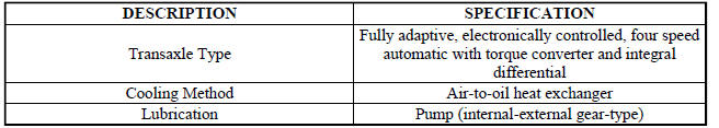
SPECIFICATIONS
GENERAL SPECIFICATIONS
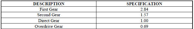
GEAR RATIOS

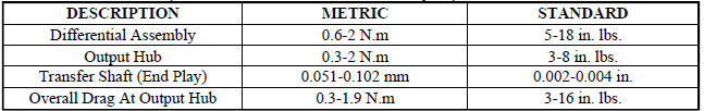
BEARING SETTINGS (END PLAY AND TURNING TORQUE)
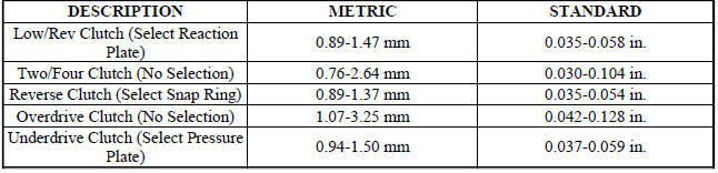
CLUTCH CLEARANCES
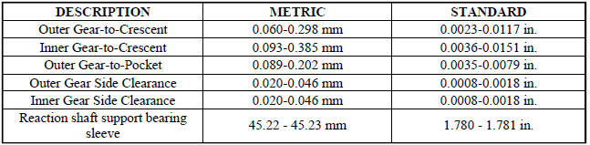
OIL PUMP CLEARANCES
INPUT SHAFT

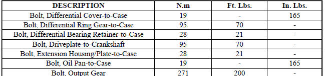
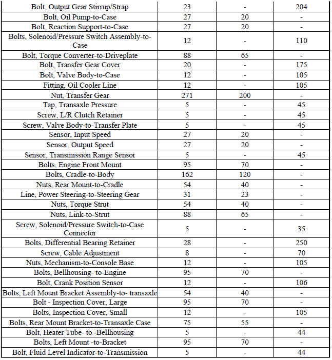
TORQUE SPECIFICATIONS
SPECIAL TOOLS
Fig. 190: Puller C-637
Fig. 191: Pressure Gauge (High) C-3293SP

Fig. 192: Dial Indicator C-3339
Fig. 193: Oil Pump Puller C-3752
Fig. 194: Seal Puller C-3981B
Fig. 195: Universal Handle C-4171
Fig. 196: Seal Installer C-4193A
Fig. 197: Adapter C-4996
Fig. 198: Remover Kit L-4406
Fig. 199: Gear Puller L-4407A
Fig. 200: Bearing Installer L-4410
Fig. 201: Gear Checking Plate L-4432
Fig. 202: Bearing Puller L-4435

Fig. 203: Differential Tool L-4436A
Fig. 204: Special Jaw Set L-4518
Fig. 205: Installer L-4520
Fig. 206: Thrust Button L-4539-2
Fig. 207: Adapter L-4559
Fig. 208: Adapter L-4559-2
Fig. 209: Bearing Splitter P-334
Fig. 210: Puller Set 5048
Fig. 211: Remover/Installer 5049-A
Fig. 212: Installer 5050A
Fig. 213: Installer 5052
Fig. 214: Compressor 5058A
Fig. 215: Compressor 5059-A
Fig. 216: Installer 5067
Fig. 217: Pliers 6051
Fig. 218: Installer 6052
Fig. 219: Installer 6053
Fig. 220: Button 6055
Fig. 221: Plate 6056
Fig. 222: Disk 6057
Fig. 223: Installer 6061
Fig. 224: Remover 6062-A
Fig. 225: Holder 6259
Fig. 226: Bolt 6260
Fig. 227: Installer 6261
Fig. 228: Tip 6268
Fig. 229: Remover/Installer 6301
Fig. 230: Remover/Installer 6302
Fig. 231: Installer 6536-A

Fig. 232: Puller 7794-A
Fig. 233: End Play Socket Set 8266
Fig. 234: Input Clutch Pressure Fixture 8391
Fig. 235: Driveline Support Table 8874
Fig. 236: Driveline Support Fixture 8534B
Fig. 237: Steering Shaft Roll Pin Remover/Installer 6831A
 Installation
Fig. 164: Removing/Installing Bellhousing Upper & Lower Bolts
NOTE: If transaxle assembly is being replaced or overhauled (clutch
and/or seal
replacement), it is necessary to perform th ...
 Accumulator
DESCRIPTION
Fig. 238: Identifying Underdrive & Overdrive Accumulators
- RETURN SPRING
- UNDERDRIVE CLUTCH ACCUMULATOR
- SEAL RING (2)
- OVERDRIVE CLUTCH ACCUMULATOR
The 41TE underd ...
See also:
Crossmember, front suspension
REMOVAL
1. Raise and support the vehicle.
Fig. 33: Tire And Wheel Mounting
2. On each side of the vehicle, remove the wheel mounting nuts (3), then the
front tire and wheel assembly
(1).
Fi ...
Removal, Installation
REMOVAL
WARNING: To avoid serious or fatal injury on vehicles equipped
with airbags, disable
the Supplemental Restraint System (SRS) before attempting any steering
wheel, steering co ...
VEHICLE LOADING
The load carrying capacity of your vehicle is shown on
the “Vehicle Certification Label.” This information
should be used for passenger and luggage loading as
indicated.
Do not exceed the spec ...
