Dodge Journey: Hydraulic pressure tests
Fig. 4: Identifying Transmission Electrical Connectors
NOTE: Before preforming the hydraulic pressure tests be certain to disconnect the Variable Line Pressure (VLP) electrical connector (2) at the transmission. Check for and clear any codes that may have been set after preforming any hydraulic pressure tests and connecting the Variable Line Pressure (VLP) electrical connector.
Fig. 5: Identifying Pressure Ports
- - OVERDRIVE CLUTCH
- - TORQUE CONVERTER OFF
- - LOW/REVERSE CLUTCH
- - 2/4 CLUTCH
- - REVERSE CLUTCH
- - UNDERDRIVE CLUTCH
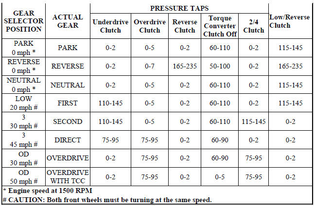
Pressure testing is a very important step in the diagnostic procedure. These tests usually reveal the cause of most hydraulic transaxle problems.
Before performing pressure tests, be certain that fluid level and condition, and shift cable adjustments have been checked and approved. Fluid must be at operating temperature 150 to 200 º F. (66 to 93 º C).
Install an engine tachometer, raise vehicle on hoist which allows front wheels to turn, and position tachometer so it can be read.
Attach 300 psi Gauge C-3293SP to port(s) (1) overdrive clutch, (2) torque converter off, (3) low/reverse clutch, (4) 2/4 clutch, (5) reverse clutch, (6) underdrive clutch required for test(s) being conducted. Use Adapter Set L- 4559 to adapt gauge(s) to transaxle.
TEST ONE-SELECTOR IN LOW (1st GEAR)
1. Attach pressure gauge to the low/reverse clutch tap.
2. Move selector lever to the (L) position.
3. Allow vehicle wheels to turn and increase throttle opening to achieve an indicated vehicle speed to 20 mph.
4. Low/reverse clutch pressure should read 115 to 145 psi.
5. This test checks pump output, pressure regulation and condition of the low/reverse clutch hydraulic circuit and shift schedule.
TEST TWO-SELECTOR IN DRIVE (2nd GEAR)
NOTE: This test checks the underdrive clutch hydraulic circuit as well as the shift schedule.
1. Attach gauge to the underdrive clutch tap.
2. Move selector lever to the 3 position.
3. Allow vehicle wheels to turn and increase throttle opening to achieve an indicated vehicle speed of 30 mph.
4. In second gear the underdrive clutch pressure should read 110 to 145 psi.
TEST TWO A-SELECTOR IN OD (4th Gear)
NOTE: This test checks the underdrive clutch hydraulic circuit as well as the shift schedule.
1. Attach gauge to the underdrive clutch tap.
2. Move selector lever to the (OD) position.
3. Allow wheels to rotate freely and increase throttle opening to achieve an indicated speed of 40 mph.
4. Underdrive clutch pressure should read below 5 psi. If not, then either the solenoid assembly or PCM/TCM is at fault.
TEST THREE-OVERDRIVE CLUTCH CHECK (3rd and 2nd Gear)
1. Attach gauge to the overdrive clutch tap.
2. Move selector lever to the (OD) position.
3. Allow vehicle wheels to turn and increase throttle opening to achieve an indicated vehicle speed of 20 mph. Vehicle should be in 3rd gear.
4. Overdrive clutch pressure should read 74 to 95 psi.
5. Move selector lever to the (3) position and increase indicated vehicle speed to 30 mph.
6. The vehicle should be in second gear and overdrive clutch pressure should be less than 5 psi.
7. This test checks the overdrive clutch hydraulic circuit as well as the shift schedule.
TEST FOUR-SELECTOR IN OVERDRIVE (4th Gear)
1. Attach gauge to the 2/4 clutch tap.
2. Move selector lever to the (OD) position.
3. Allow vehicle front wheels to turn and increase throttle opening to achieve an indicated vehicle speed of 30 mph. Vehicle should be in 4th gear.
4. The 2/4 clutch pressure should read 75 to 95 psi.
5. This test checks the 2/4 clutch hydraulic circuit.
TEST FIVE-SELECTOR IN OVERDRIVE (4th Gear-CC on)
1. Attach gauge to the torque converter clutch off pressure tap.
2. Move selector lever to the (OD) position.
3. Allow vehicle wheels to turn and increase throttle opening to achieve an indicated vehicle speed of 50 mph. Vehicle should be in 4th gear, CC on.
CAUTION: Both wheels must turn at the same speed.
4. Torque converter clutch off pressure should be less than 5 psi.
5. This test checks the torque converter clutch hydraulic circuit.
TEST SIX-SELECTOR IN REVERSE
1. Attach gauges to the reverse and LR clutch tap.
2. Move selector lever to the (R) position.
3. Read reverse clutch pressure with output stationary (foot on brake) and throttle opened to achieve 1500 RPM.
4. Reverse and LR clutch pressure should read 165 to 235 psi.
5. This test checks the reverse clutch hydraulic circuit.
TEST RESULT INDICATIONS
1. If proper line pressure is found in any one test, the pump and pressure regulator are working properly.
2. Low pressure in all positions indicates a defective pump, a clogged filter, or a stuck pressure regulator valve.
3. Clutch circuit leaks are indicated if pressures do not fall within the specified pressure range.
4. If the overdrive clutch pressure is greater than 5 psi in 4 of Test Three, a worn reaction shaft seal ring or a defective solenoid assembly is indicated.
5. If the underdrive clutch pressure is greater than 5 psi in 4 of Test Two A, a defective solenoid assembly or PCM/TCM is the cause.
PRESSURE CHECK SPECIFICATIONS
 40/41TE Transaxle general diagnosis, road test
40/41TE TRANSAXLE GENERAL DIAGNOSIS
NOTE: Before attempting any repair on a 40/41TE four-speed automatic
transaxle,
check for Diagnostic Trouble Codes (DTC's) using the scan tool.
Transaxl ...
 Clutch air pressure tests
Fig. 6: Identifying Air Pressure Test Plate Tool 6056
- AIR PRESSURE TEST PLATE TOOL 6056
- ACCUMULATORS
Inoperative clutches can be located using a series of tests by substituting
air pr ...
See also:
Installation
BULB
Each rear lamp unit for this vehicle consists of two pieces. An outer rear
lamp unit that is secured at the rear of
each quarter panel includes bulbs for the park (or tail) lamps, the brake ( ...
Operation
Fig. 427: Identifying Torque Converter Fluid Pressure
Operation
- APPLY PRESSURE
- THE PISTON MOVES SLIGHTLY
FORWARD
- RELEASE PRESSURE
- THE PISTON MOVES SLIGHTLY
REARWARD
The co ...
Cam, turn signal cancel
DESCRIPTION
The turn signal cancel cam is concealed within the clockspring case on the
steering column. The turn signal
cancel cam consists of integral eccentrics on the outer circumference of the ...
