Dodge Journey: Toe
Fig. 115: Steering Wheel Holding Tool
1. Center the steering wheel and lock it in place using a steering wheel clamp.
NOTE: When setting toe, make sure to set rear toe to the preferred specifications before setting front toe to the preferred specifications
NOTE: Perform the following at each rear wheel as necessary.
Fig. 116: Rear Toe Adjustment Cam Bolt
NOTE: Perform the following at each front wheel as necessary.
CAUTION: Do not twist the inner tie rod-to-steering gear boot (bellows) while turning the inner tie rod during front toe adjustment. It may be necessary to remove the clamp where the boot meets the inner tie rod.
Fig. 117: Tie Rod Jam Nut
REAR TOE
NOTE: Perform the following at each rear wheel as necessary.
Fig. 118: Rear Toe Adjustment Cam Bolt
2. While holding the cam bolt head (4) stationary, loosen the toe link mounting cam bolt nut (3).
3. Rotate the cam bolt head (4) left or right until the rear wheel toe for that rear wheel is set to the preferred specification. 4. While holding the cam bolt head (4) stationary, tighten the toe link mounting cam bolt nut (3) to 100 N.m (74 ft. lbs.).
FRONT TOE
NOTE: Perform the following at each front wheel as necessary.
CAUTION: Do not twist the inner tie rod-to-steering gear boot (bellows) while turning the inner tie rod during front toe adjustment. It may be necessary to remove the clamp where the boot meets the inner tie rod.
Fig. 119: Tie Rod Jam Nut
5. Loosen the tie rod adjusting jam nut (1). Grasp the inner tie rod (3) and rotate it one way or the other until the front wheel toe is set to the preferred specification.
6. Tighten the tie rod adjusting jam nut to of 75 N.m (55 ft. lbs.).
7. Make sure the inner tie rod-to-steering gear boot is not twisted. If removed, reinstall the clamp where the boot meets the inner tie rod.
ALL
8. Remove the steering wheel clamp.
9. Remove the alignment equipment.
10. Road test the vehicle to verify the steering wheel is straight and the vehicle does not pull or wander.
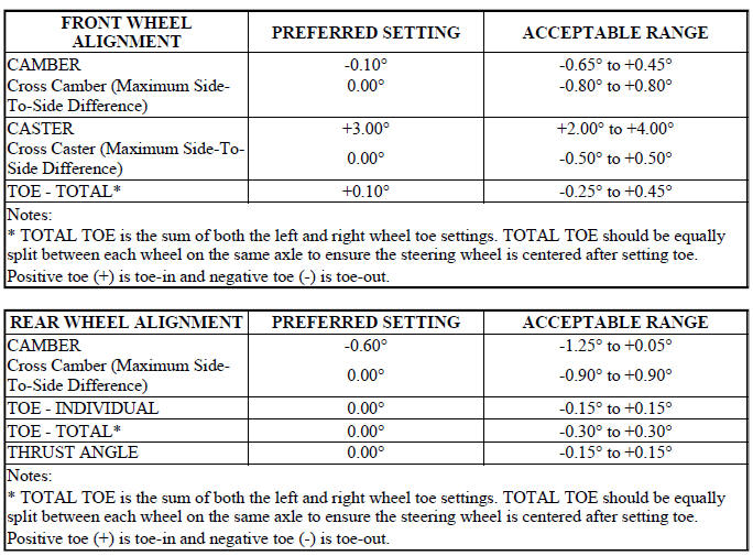
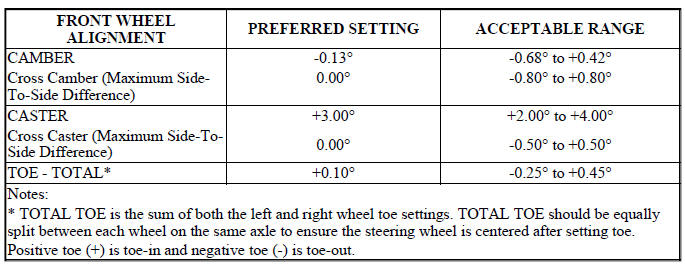
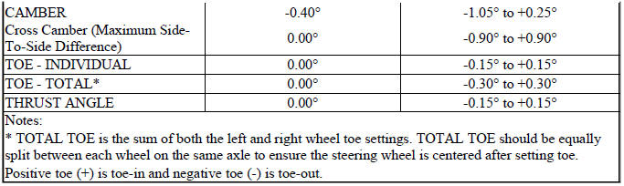
SPECIFICATIONS
WHEEL ALIGNMENT
NOTE: All specifications are given in degrees.
NOTE: All wheel alignments are to be set with the vehicle at curb height.
NOTE: Curb (ride) height specifications can be found in the Curb Height Measurement procedure.
ALL EXCEPT EXPORT
EXPORT

 Wheel alignment
PRE-WHEEL ALIGNMENT INSPECTION
Before any attempt is made to change or correct the wheel alignment, the
following inspection and necessary
corrections must be made to the vehicle to ensure proper ...
 Transmission
...
See also:
Standard procedure
BASE BRAKE BLEEDING
NOTE: This bleeding procedure is only for the vehicle's base brakes
hydraulic system.
For bleeding the antilock brakes hydraulic system.
CAUTION: Before removing t ...
Cleaning, inspection
CLEANING
To ensure engine gasket sealing, proper surface preparation must be
performed, especially with the use of
aluminum engine components and multi-layer steel cylinder head gaskets.
NOTE: ...
Installation
2.4L
Fig. 17: Removing/Installing Ignition Coil
1. Install ignition coil onto spark plug.
Fig. 18: Removing/Installing Ignition Coil Mounting Bolts
2. Install ignition coil mounting bolt, tigh ...
