Dodge Journey: Arm, lower control
Diagnosis and Testing
LOWER CONTROL ARM
Inspect the lower control arm for signs of damage from contact with the ground or road debris. If the lower control arm shows any sign of damage, look for distortion. Do not attempt to repair or straighten a broken or bent lower control arm. If damaged, the lower control arm is serviced only as a complete component.
Inspect both lower control arm isolator bushings for severe deterioration and replace the lower control arm as required.
Removal
1. Raise and support the vehicle.
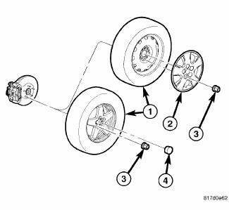
Fig. 7: TIRE AND WHEEL MOUNTING
2. Remove the wheel mounting nuts (3), then the tire and wheel assembly (1).
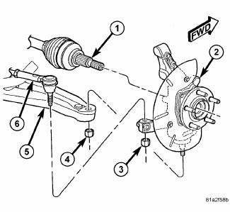
Fig. 8: Front Knuckle Mounting
3. Remove the nut (4) attaching the lower ball joint to the lower control arm (5).
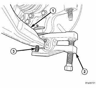
Fig. 9: Using 9360 On Lower Ball Joint
4. Release the lower ball joint (3) from the lower control arm (1) using Remover (2) 9360. Do not lift the knuckle out of the lower control arm at this time.
CAUTION: Upon removing the knuckle from the ball joint stud, do not pull outward on the knuckle. Pulling the knuckle outward at this point can separate the inner C/V joint on the half shaft thus damaging it.
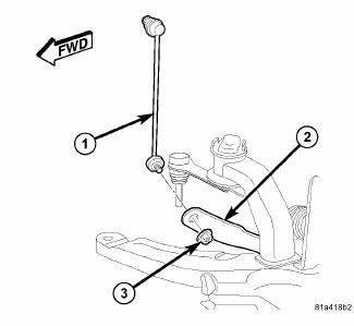
Fig. 10: Stabilizer Link Mounting To Bar
5. At each end of the stabilizer bar, while holding the stabilizer bar link (1) lower stud stationary, remove the nut (3) securing the link to the stabilizer bar (2).
6. Rotate the ends of the stabilizer bar (2) upward away from the lower control arm.
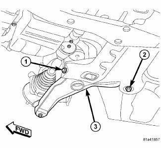
Fig. 11: Lower Control Arm Mounting
7. Remove the front bolt (1) attaching the lower control arm (3) to the front suspension crossmember.
8. Remove the nut on the rear bolt (2) attaching the lower control arm (3) to the front suspension crossmember. Remove the bolt.
9. Remove the lower control arm (3) from the crossmember.
Installation
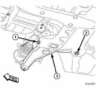
Fig. 12: Lower Control Arm Mounting
1. Place the lower control arm (3) into the front suspension crossmember.
2. Insert the rear bolt (2) up through the crossmember and lower control arm (3). Install the nut on the topend of the bolt, but do not tighten it at this time.
3. Install, but do not fully tighten, the front bolt (1) attaching the lower control arm (3) to the crossmember.
4. With no weight or obstruction on the lower control arm, tighten the lower control arm front mounting bolt (1) to 200 N.m (148 ft. lbs.).
5. With no weight or obstruction on the lower control arm, tighten the lower control arm rear mounting bolt nut to 145 N.m (107 ft. lbs.).
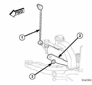
Fig. 13: Stabilizer Link Mounting To Bar
6. Attach the stabilizer bar link (1) at each end of the stabilizer bar (2). At each link, install and tighten the nut (3) while holding the stabilizer bar link lower stud stationary. Tighten the nuts to 48 N.m (35 ft. lbs.).
NOTE: If a new or cleaned lower control arm is being installed, it is important to have a film of general purpose grease around the ball joint mounting hole on the lower control arm to avoid any future corrosion issues. Make sure the grease does not get inside the ball joint mounting hole or on the ball joint stud during installation.
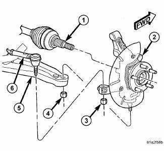
Fig. 14: Front Knuckle Mounting
7. Insert the lower ball joint stud into the mounting hole in the lower control arm (5).
8. Install a NEW ball joint stud nut (4). Tighten the nut to 95 N.m (70 ft. lbs.).
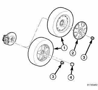
Fig. 15: TIRE AND WHEEL MOUNTING
9. Install the tire and wheel assembly (1). Install and tighten the wheel mounting nuts (3) to 135 N.m (100 ft. lbs.).
10. Lower the vehicle.
11. Perform wheel alignment as necessary.
 Description
Fig. 1: Front Suspension Components
This vehicle has a gas pressurized MacPherson strut type front suspension
design.
Each side of the front suspension consists of these major components:
...
See also:
Ring(s), piston
Standard Procedure
PISTON RING FITTING
Fig. 200: CHECK GAP ON PISTON RINGS
- FEELER GAUGE
1. Wipe cylinder bore clean. Insert ring and push down with piston to ensure
it is square in bore ...
Description, Operation
DESCRIPTION
CAUTION: Grid lines can be damaged or scraped off with sharp
instruments. Care
should be taken in cleaning glass or removing foreign materials, decals or
stickers. Normal glass ...
Description
The parking brake consists of the following components:
Foot-operated parking brake lever *
Cables (front, left rear, right rear)
Cable equalizer
Caliper with Integral Parking Brake (IPB)
...

