Dodge Journey: Installation
CAUTION: Be certain to adjust the refrigerant oil level when servicing the A/C refrigerant system. Failure to properly adjust the refrigerant oil level will prevent the A/C system from operating as designed and can cause serious A/C compressor damage.
NOTE: When replacing multiple A/C system components, refer to the REFRIGERANT OIL CAPACITIES to determine how much oil should be added to the refrigerant system. NOTE: Replacement of the refrigerant line O-ring seals is required anytime an underbody refrigerant line is disconnected. Failure to replace the rubber O-ring seals may result in a refrigerant system leak.
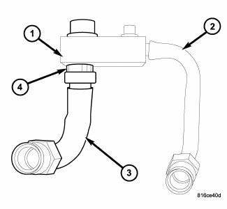
Fig. 304: Underbody Suction Extension Line
1. If removed, install the suction extension line (3) into the sealing plate (1) and install the nylon retaining clip (4).
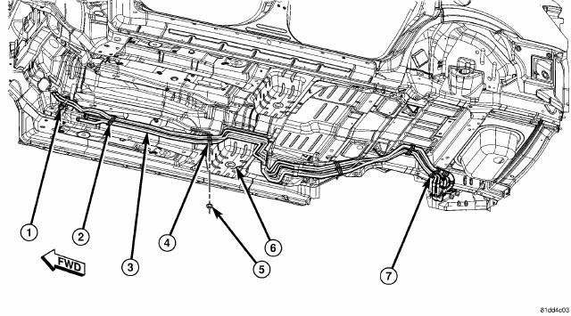
Fig. 305: Underbody Line Brackets
NOTE: Illustration shown with rear body cradle removed for clarity.
2. Position the underbody lines (3) and engage the underbody line brackets (1, 2, and 7) to the mounting studs located on the underbody (6). Rotate and tilt the underbody lines as necessary. Make sure the brackets are fully engaged to the studs.
3. Position the underbody line bracket (4) onto the mounting stud located near the center of the underbody and install the retaining nut (5). Tighten the nut securely.
CAUTION: Use care not to damage the ABS wire lead or the brake line when repositioning the rear cradle.
4. Carefully raise the jack stand until the right side of the rear cradle is positioned to the body.
WARNING: Be sure to properly support the rear cradle when installing the right side retaining bolts. Failure to follow this warning may result in serious or fatal injury.
5. Install the bolts that secure the right side of the cradle to the body and remove the jack stand.
6. Install the lower right rear shock retaining bolt.
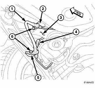
Fig. 306: Right Rear Brake Line Brackets & Wire Harness
7. Connect the rear ABS wire harness lead and bracket (4) to the right side of the body (3).
8. Position the right rear brake line (1) onto the two brackets (2 and 5) and install the two retaining bolts (6).
Tighten the bolts securely.
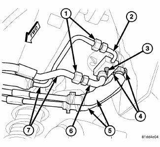
Fig. 307: Underbody Lines to Rear Housing
CAUTION: DO NOT apply excessive force on underbody heater lines or rear heater tubes fittings when connecting the connections. Excessive force may damage or deform the tubes and or lines, causing an engine coolant leak.
NOTE: Replacement of the rubber heater hose ends will be required if the rubber hoses were cut for removal.
9. Remove the tape or plugs from all the opened refrigerant line fittings and the rear expansion valve ports.
10. Lubricate new rubber O-ring seals with clean refrigerant oil and install them onto the underbody refrigerant extension line fittings. Use only the specified O-rings as they are made of a special material for the R-134a refrigerant system. Use only refrigerant oil of the type recommended for the A/C compressor in the vehicle.
11. Connect the underbody refrigerant extension lines and sealing plate (2 and 6) to the rear A/C expansion valve.
12. Loosely install the nut (3) that secures the extension lines and sealing plate to the rear A/C expansion valve.
13. Connect the underbody refrigerant lines (7) to the underbody refrigerant extension lines and tighten the fitting nuts (1) to 23 N.m (17 ft. lbs.).
14. Tighten the nut that secures the extension lines and sealing plate to the rear A/C expansion valve to 11 N.m (97 in. lbs.).
15. Connect the underbody heater lines (5) to the rear heater core tubes located behind the right rear wheel housing and engage the spring type hose clamps (4).
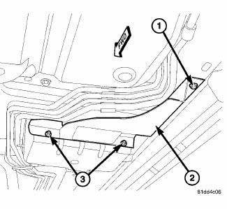
Fig. 308: Underbody Line Shield
16. Position the underbody line shield (2) to the vehicle underbody and install the two nuts (3) and one screw (1). Tighten the fasteners securely.
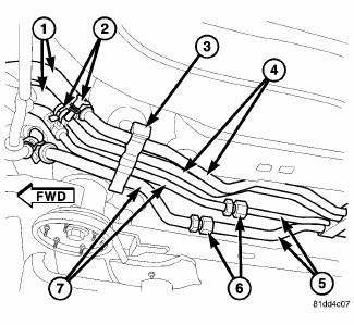
Fig. 309: Underbody Lines Front Connections
17. Lubricate new rubber O-ring seals with clean refrigerant oil and install them onto the underbody refrigerant line fittings. Use only the specified O-rings as they are made of a special material for the R- 134a refrigerant system. Use only refrigerant oil of the type recommended for the A/C compressor in the vehicle.
18. Connect the front A/C liquid and suction lines (7) to the underbody refrigerant lines (5). Tighten the fitting nuts (6) to 23 N.m (17 ft. lbs.).
19. Position the front A/C liquid and suction lines into the front underbody refrigerant line bracket (3) and engage the bracket retainer.
NOTE: Replacement of the front heater hoses will be required if the hose ends were cut for removal.
20. Connect the front heater hoses (1) to the underbody heater lines (4) and engage the spring type hose clamps (2).
21. Install the exhaust heat shields as necessary.
22. Install the rear section of the exhaust system.
23. Lower the vehicle.
24. Reconnect the negative battery cable.
25. Fill the engine cooling system.
26. Evacuate the refrigerant system.
27. Adjust the refrigerant oil level.
28. Charge the refrigerant system.
 Removal
WARNING: Refer to the applicable warnings and cautions for this
system before
performing the following operation. Failure to follow these instructions
may
result in serious or fat ...
 Lines, A/C underbody, extension
Description
Fig. 310: Underbody A/C Extension Lines Description
Models equipped with the rear heating-A/C system use metal lines attached to
the vehicle underbody to carry
refrigerant and engin ...
See also:
INSTRUMENT CLUSTER
INSTRUMENT CLUSTER ...
Sensor, coolant temperature
Description
There are two Engine Coolant Temperature (ECT) Sensors. One of the sensors
threads into the block. The other
sensor is located at the top of the coolant adapter housing. The ECT Sensor ...
Tube, exhaust gas recirculation (EGR)
Removal
2.7L - LOWER TUBE
Fig. 50: Lower Exhaust Gas Recirculation Tube - 2.7L
WARNING: The normal operating temperature of the exhaust gas
recirculate (EGR)
valve and tube is very ...
