
Dodge Journey: Description
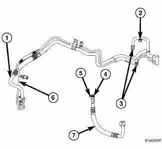
Fig. 253: Upper Suction/Liquid Line Assembly
NOTE: A/C Suction line for 2.7L engine shown. Other engines similar.
The A/C suction line carries refrigerant from the A/C expansion valve to the A/C compressor and is serviced in two sections. The upper section of the A/C suction line (1) includes the low side service port (2) and is only serviced as an assembly with the rear A/C liquid line (6). When equipped with rear A/C, the A/C liquid and suction line assembly includes connections for the underbody refrigerant lines (3). The lower section of the A/C suction line (7) connects to the upper section of the suction line and the connections are sealed by use of metal gaskets (5) and rubber O-ring seals (4)
NOTE: Replacement of the refrigerant line O-ring seals and gaskets is required anytime a refrigerant line is disconnected. Failure to replace the rubber O-ring seals and metal gaskets could result in a refrigerant system leak.
The lower A/C suction line and the A/C liquid and suction line assembly has no serviceable parts except for the metal gaskets, rubber O-ring seals and the service port valve cores. The O-ring seals used on the connections are made from a special type of rubber not affected by R-134a refrigerant. The O-ring seals and gaskets must be replaced whenever the lower A/C suction line and/or the A/C liquid and suction line assembly is disconnected.
The lower A/C suction line and the A/C liquid and suction line assembly cannot be repaired and must be replaced if leaking or damaged.

 Removal
WARNING: Review safety precautions and warnings in this part
before performing
this procedure. See Heating and Air Conditioning/Plumbing - Warning
and. Failure to
follow the warnin ...
See also:
Description, Operation
DESCRIPTION
The EGR system reduces oxides of nitrogen (NOx) in the engine exhaust. This
is accomplished by allowing a
predetermined amount of hot exhaust gas to recirculate and dilute the incoming ...
Cover(s), cylinder head, right
REMOVAL
1. Disconnect negative battery cable.
Fig. 126: Engine Harness Retaining Clips
- Left cylinder head cover engine harness retainers
- Right cylinder head cover engine harness retainer ...
Monitor, media system
REMOVAL
Fig. 14: Removing / Installing Mounting Fasteners
1. Disconnect and isolate the battery negative cable.
2. Open the video screen to access the mounting fasteners.
3. Remove the mount ...
