Dodge Journey: Inspection
CLUTCH INSPECTION - FIXED DISPLACEMENT A/C COMPRESSOR

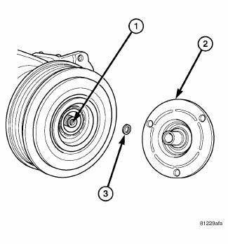
Fig. 212: Identifying Compressor Shaft, Clutch Plate & Shim
Examine the friction surfaces of the pulley and the clutch plate (2) for wear. The pulley and clutch plate should be replaced if there is excessive wear or scoring.
If the friction surfaces are oily, inspect the shaft and nose area of the A/C compressor (1) for refrigerant oil. If refrigerant oil is found, the compressor shaft seal is leaking and the A/C compressor must be replaced.
Check the pulley bearing for roughness or excessive leakage of grease. Replace the pulley and clutch plate if required.
HUB AND PULLEY INSPECTION - VARIABLE DISPLACEMENT A/C COMPRESSOR
NOTE: The compressor drive hub and the pulley and bearing assembly can not be serviced separately from the A/C compressor. In the event of drive hub or pulley and bearing assembly damage or failure, the A/C compressor, drive hub and pulley and bearing must be replaced as an assembly.

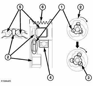
Fig. 213: Compressor Hub & Pulley Inspection
NOTE: Typical clutchless compressor drive hub and pulley and bearing assembly shown.
The bridges (1) located on the non-servicable compressor hub (2) are designed to break away in the event of compressor seizure. Examine the bridges for separation or cracks (3). Damage to the bridges are an indication of excessive compressor torque, which is most likely caused by compressor failure.
Check the non-servicable pulley bearing (4) for roughness or excessive noise. Check the pulley dampeners (5) for excessive play which can be caused by deterioration or damage. Inspect the belt surfaces of the nonservicable pulley (4) for wear. If the pulley surfaces are oily, inspect the shaft and nose area of the A/C compressor for refrigerant oil. If refrigerant oil is found, the compressor shaft seal is leaking and the A/C compressor must be replaced.
Replace the A/C compressor if wear or damage is found to the drive hub or pulley and bearing assembly.
 Removal
CLUTCH - FIXED DISPLACEMENT A/C COMPRESSOR
WARNING: Refer to the applicable warnings and cautions for this
system before
performing the following operation. Failure to follow the warnin ...
 Installation
CLUTCH - FIXED DISPLACEMENT A/C COMPRESSOR
NOTE: Typical A/C compressor and clutch assembly shown in
illustrations.
Fig. 214: Clutch Coil & Snap Ring
1. Align the dowel pin on the bac ...
See also:
Relay, heater unit
DESCRIPTION
Fig. 320: Standard ISO-Type Relay
Three relays (1) are used for the electric positive temperature coefficient (PTC)
heater system when equipped
with the 2.0L diesel engine. The rela ...
Specifications
2.7L ENGINE
GENERAL SPECIFICATIONS
CYLINDER BLOCK
PISTONS
PISTON PINS
PISTON RINGS
PISTON RING SIDE CLEARANCE
PISTON RING WIDTH
CONNECTING RODS
CRANKSHAFT MA ...
Switch, hazard warning
DESCRIPTION
Fig. 44: Instrument Panel Switch Pod
The hazard switch (3) is integral to the instrument panel switch pod (1),
which is secured to the instrument
panel center bezel just above the h ...
