Dodge Journey: Transducer, A/C pressure
DESCRIPTION

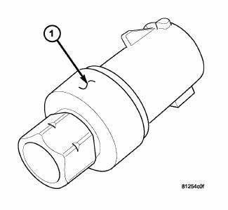
Fig. 44: A/C Pressure Transducer
- - A/C PRESSURE TRANSDUCER
The A/C pressure transducer (1) is a switch that is installed on a fitting located on the A/C liquid line at the right front corner of the engine compartment. An internally threaded fitting on the A/C pressure transducer connects it to the externally threaded Schrader-type fitting. A rubber O-ring seals the connection between the A/C pressure transducer and the A/C liquid line fitting. The A/C pressure transducer is connected to the vehicle electrical system by a molded plastic connector with three terminals.
OPERATION
The A/C pressure transducer monitors the pressures in the high side of the refrigerant system through its connection to a fitting on the A/C discharge line. The internal resistance of the A/C pressure transducer changes in response to the pressures it monitors.
The Totally Integrated Power Module (TIPM) provides a five volt reference signal and a sensor ground to the A/C pressure transducer. The TIPM then monitors the output voltage of the transducer on a sensor return circuit to determine refrigerant pressure and sends a message to the Powertrain Control Module (PCM) or the Engine Control Module (ECM) (depending on engine application) over the CAN C BUS.
With 2.7L/3.5L 5-Passenger and all 7-Passenger models, the PCM is programmed to respond to this and other sensor inputs by controlling the operation of the swash plate within the A/C compressor and the radiator cooling fan to help optimize A/C system performance and to protect the system components from damage. The PCM adjusts the swash plate to nearly a zero degree angle (low compressor displacement) when high side pressure rises above 3130 kPa (454 psi) and readjusts the swash plate to a greater angle (higher compressor displacement) when high side pressure drops below 1999 kPa (290 psi). The A/C pressure transducer also reduces the swash plate angle if the high side pressure drops below 200 kPa (29 psi) and will increase the swash plate angle when the high side pressure rises above 234 - 262 kPa (34 - 38 psi). When the refrigerant pressure rises above 1655 kPa (240 psi), the PCM will actuate the cooling fan.
With 2.0L/2.4L 5-Passenger models, A/C compressor clutch engagement is controlled by the PCM or ECM, depending on engine application. When the A/C-heater control is set to any A/C position, it sends a request signal on the CAN-IHS bus to the TIPM, which then transfers the request on the CAN-C Bus to the PCM/ECM, which determines if operating conditions are correct for A/C clutch engagement. When all operating conditions have been met, the PCM/ECM sends a signal on a dedicated hard-wired circuit back to the TIPM to energize the internal A/C clutch high side driver. When energized, the A/C clutch high side driver provides battery current to the A/C clutch field coil.
A Schrader-type valve in the A/C discharge line fitting permits the A/C pressure transducer to be removed or installed without disturbing the refrigerant in the A/C system.
The A/C pressure transducer is diagnosed using a scan tool.
The A/C pressure transducer cannot be adjusted or repaired and must be replaced if inoperative or damaged.
REMOVAL
WARNING: Refer to the applicable warnings and cautions for this system before performing the following operation. Failure to follow the warnings and cautions may result in possible serious or fatal injury.
NOTE: It is not necessary to discharge the refrigerant system to replace the A/C pressure transducer.

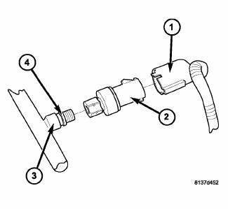
Fig. 45: Transducer-A/C pressure Removal/Installation
NOTE: Typical A/C pressure transducer shown.
1. Disconnect and isolate the negative battery cable.
2. Disconnect the wire harness connector (1) from the A/C pressure transducer (2) located on the A/C liquid line (3) at the right front corner of the engine compartment.
3. Remove the A/C pressure transducer from the A/C liquid line and remove and discard the O-ring seal (4).
INSTALLATION
NOTE: Use only the specified O-ring as it is made of special material for R-134a. Use only refrigerant oil of the type required for the A/C compressor.

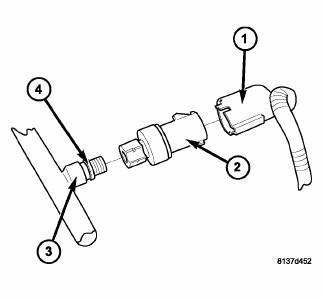
Fig. 46: Transducer-A/C pressure Removal/Installation
NOTE: Typical A/C pressure transducer shown.
1. Lubricate a new rubber O-ring seal (4) with clean refrigerant oil and install it onto the A/C liquid line (3).
2. Install the A/C pressure transducer (2) onto the A/C liquid line. Tighten the A/C pressure transducer to 5.6 N.m (50 in. lbs.).
3. Connect the wire harness connector (1) to the A/C pressure transducer.
4. Reconnect the negative battery cable.
 Sensor, sun
DESCRIPTION
Fig. 40: Sensor-Sun
NOTE: Typical sun sensor assembly shown.
The automatic temperature control (ATC) heating-A/C system uses a sun sensor
assembly (1) to measure sun
light int ...
 Controls, rear
...
See also:
Description, Operation
DESCRIPTION
There are two different batteries available for this vehicle. Vehicles
equipped with a diesel engine utilize a
spiral cell battery with recombination technology. This is a maintenance- ...
Description
Vehicle wheel alignment is the positioning of all interrelated front and rear
suspension angles. These angles
affect the handling and steering of the vehicle when it is in motion. Proper
wheel al ...
CHILL ZONE BEVERAGE COOLER STORAGE COMPARTMENT
The Chill Zone Beverage Cooler Storage Compartment
can keep chilled beverages cool depending on ambient
temperature and climate control setting. Chill Zone is
intended for nonperishable beverages o ...
