Dodge Journey: Resistor, blower motor, front
DESCRIPTION
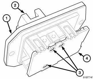
Fig. 30: Blower Motor Resistor - Description
A blower motor resistor is used on vehicles equipped with the manual temperature control (MTC) heating-A/C system. Vehicles equipped with the automatic temperature control (ATC) heating-A/C system use a blower motor power module, instead of the blower motor resistor. The blower motor resistor is mounted to the bottom of the HVAC housing, on the passenger side of the vehicle.
The blower motor resistor consists of a molded plastic mounting plate (1) with an integral wire connector receptacle (2). Concealed behind the mounting plate are resistors (3) located between a two-piece stamped steel base (4). The blower motor resistor is accessed for service from under the instrument panel.
OPERATION
The blower motor resistor is connected to the vehicle electrical system through a dedicated take out and connector of the instrument panel wire harness. The blower motor resistor has three resistors, each of which will reduce the current flow through the blower motor to change the blower motor speed.
The blower motor control for the heating-A/C system directs the ground path for the blower motor through the correct resistor to obtain the selected speed. With the blower motor control in the lowest speed position, the ground path for the blower motor is applied through all of the resistors. Each higher speed selected with the blower motor control applies the blower motor ground path through fewer of the resistors, increasing the blower motor speed. When the blower motor control is in the highest speed position, the blower motor resistor is bypassed and the blower motor receives a direct path to ground.
The blower motor resistor cannot be adjusted or repaired and it must be replaced if inoperative or damaged.
Diagnosis and Testing
BLOWER MOTOR RESISTOR
WARNING: Disable the airbag system before attempting any steering wheel, steering column or instrument panel component diagnosis or service. Disconnect and isolate the negative battery (ground) cable, then wait two minutes for the airbag system capacitor to discharge before performing further diagnosis or service. This is the only sure way to disable the airbag system. Failure to follow these instructions may result in accidental airbag deployment and possible serious or fatal injury.
NOTE: See SYSTEM WIRING DIAGRAMS for circuit descriptions and diagrams. Wiring Information includes wiring diagrams, proper wire and connector repair procedures, further details on wire harness routing and retention, as well as pin-out and location views for the various wire harness connectors, splices and grounds.
1. Disconnect and isolate the negative battery cable.
2. Disconnect the wire harness connector from the blower motor resistor. 3. Using an ohmmeter, check for continuity between all of the blower motor resistor terminals. In each case there should be continuity. If OK, repair the wire harness circuits between the blower motor speed control and the blower motor resistor or blower motor as required. If not OK, replace the inoperative blower motor resistor.
REMOVAL
WARNING: Disable the airbag system before attempting any steering wheel, steering column or instrument panel component diagnosis or service. Disconnect and isolate the negative battery (ground) cable, then wait two minutes for the airbag system capacitor to discharge before performing further diagnosis or service. This is the only sure way to disable the airbag system. Failure to follow these instructions may result in accidental airbag deployment and possible serious or fatal injury.
WARNING: The blower motor resistor may get very hot during normal operation. If the blower motor was turned on prior to servicing the blower motor resistor, wait five minutes to allow the blower motor resistors to cool before performing diagnosis or service. Failure to take this precaution may result in possible injury.
CAUTION: Do not operate the blower motor with the blower motor resistor removed from the circuit. Failure to take this precaution can result in vehicle damage.
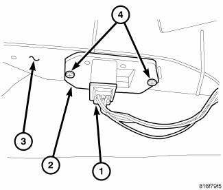
Fig. 31: Blower Motor Resistor
NOTE: LHD model shown. RHD model similar.
1. Disconnect and isolate the negative battery cable.
2. Disconnect the wire harness connector (1) from the blower motor resistor (2) located at the bottom of the HVAC housing (3) on the passenger side of the vehicle.
3. Remove the two screws (4) that secure the blower motor resistor to the HVAC housing and remove the resistor.
INSTALLATION

Fig. 32: Blower Motor Resistor
NOTE: LHD model shown. RHD model similar.
1. Position the blower motor resistor (2) onto the bottom of the HVAC housing (3).
2. Install the two screws (4) that secure the blower motor resistor to the HVAC housing. Tighten the screws to 1.2 N.m (10 in. lbs.).
3. Connect the wire harness connector (1) to the blower motor resistor.
4. Reconnect the negative battery cable.
 Module, power, front blower motor
DESCRIPTION
Fig. 27: Blower Mtr Pwr Module
A blower motor power module is used on this model when equipped with the
automatic temperature control (ATC) heating-A/C system. Models equipped with t ...
 Sensor, ambient temperature
DESCRIPTION
Fig. 33: Identifying Ambient Air Temperature Sensor
The ambient air temperature sensor is a variable resistor that monitors the
air temperature outside of the vehicle.
The ATC sys ...
See also:
Description, Diagnosis and Testing
Description
Fig. 17: PEDAL AND BOOSTER MOUNTING - LHD
The power brake booster (3) is mounted to the engine side of the dash panel.
The master cylinder is bolted to
the front of the booster. A v ...
Removal
WARNING: Review safety precautions and warnings in this part
before performing
this procedure. Failure to
follow the warnings and cautions could result in possible serious or
fata ...
Radio
STANDARD PROCEDURE
RADIO BACKUP
The radio hard disk drive (HDD) can be backed up to save customer data in the
event that a radio replacement is
required. This procedure can only be done with all ...
