Dodge Journey: Plug, glow
DESCRIPTION

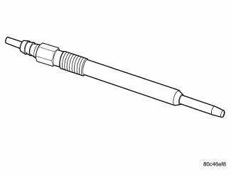
Fig. 26: Glow Plug
Glow plugs are used to help start a cold or cool engine. The glow plugs will heat up and glow to heat the combustion chamber of each cylinder. An individual glow plug is used for each cylinder. Each glow plug is threaded into the cylinder head below the cylinder head cover.
OPERATION
The glow plugs are used to preheat the combustion chambers in order to achieve the ignition temperature required for the fuel-air mixture.
The heating element is integrated in the glow rod. It consists of a heating winding and a control winding connected in series.
The glow plug system is a quick start type. This allows for immediate start in practically all weather conditions without long periods of preglowing. This works in conjunction with 6-hole injectors, which have a special "ignition" spray pattern. The glow plugs reach 1000º C (1832º F) in 2 seconds.
REMOVAL

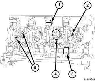
Fig. 27: Glow Plugs
NOTE: If replacing a one or more glow plugs that failed, check the glow plug relay control circuit (K202) for a short to voltage. Back probe circuit (K202) between the engine control module and the glow plug control module. Any reading higher than 9.8 volts with the key on would be considered a short to voltage.
1. Disconnect negative battery cable.
2. Remove engine cover.
3. Remove cylinder head cover.
4. Disconnect glow plug electrical connector.
5. Remove glow plugs (2) from cylinder head.
INSTALLATION

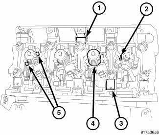
Fig. 28: Glow Plugs
1. Clean glow plug bay and install glow plug.
2. Tighten glow plugs to 10 N.m (89 lbs. in.).
3. Connect glow plug electrical connector.
4. Install cylinder head cover.
5. Install engine cover.
6. Connect negative battery cable.
 Module, glow plug
DESCRIPTION
Fig. 23: Locating Diesel Glow Plug Control Module
The glow plug control module is mounted to the fuel filter/water separator
bracket, and is controlled by the
engine control module. ...
See also:
Fascia, rear
REMOVAL
Fig. 15: Push Pins
1. Open the hatch.
2. Remove the 6 pushpins (1) securing the fascia (2).
Fig. 16: Rivets
3. Remove the rivets (2) and the Torx screw (3) around the wheel well for ...
ELECTRONIC BRAKE CONTROL SYSTEM
Your vehicle is equipped with an advanced electronic
brake control system commonly referred to as ESP. This
system includes Anti-Lock Brake System (ABS), Brake
Assist System (BAS), Traction Control ...
Pod, switch
DESCRIPTION
Fig. 10: Accessory Switch Bank Module
The Accessory Switch Bank Module (ASBM) is located in the center stack area
of the instrument panel just
below the heater and air conditioner d ...

