Dodge Journey: Switch, evaporative emissions system monitor
Operation
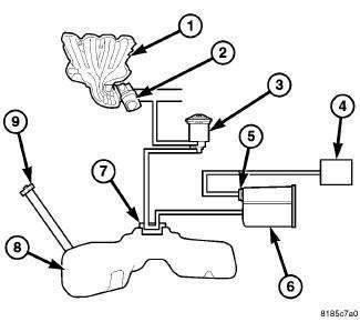
Fig. 29: Evaporative Emissions System Monitor Switch
- - Intake Manifold
- - Throttle Body
- - Purge Solenoid
- - Filter
- - ESIM
- - Vapor Canister
- - Control Valve
- - Fuel Tank
- - Gas Cap
The ESIM (Evaporative System Integrity Monitor) is very similar to the NVLD. However, the design of the ESIM has been simplified and unlike the NVLD the ESIM does not require a solenoid. The ESIM mounts directly to the canister, eliminating the need for a mounting bracket. It is critical that the ESIM is mounted vertically. On vehicles where the canister is mounted on an angle, the ESIM requires an adaptor to maintain a vertical position. When the ESIM is installed vertically, the electrical connector is in the 3 o'clock position.
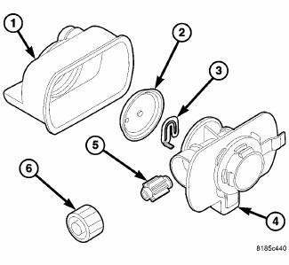
Fig. 30: EXPLODED VIEW
- - ESIM Housing
- - Diaphragm
- - Switch
- - Cover
- - Small Check Valve
- - Large Check Valve
The ESIM assembly consists of a housing, a small weight and a large weight that serve as check valves, a diaphragm, a switch and a cover. There is one large weight and one small weight check valve in the ESIM assembly. A seal is attached at the end of each weighted check valve. The large weight check valve seals for pressure. The small weight check valve seals for vacuum. The weighted check valves are contained within the ESIM housing.
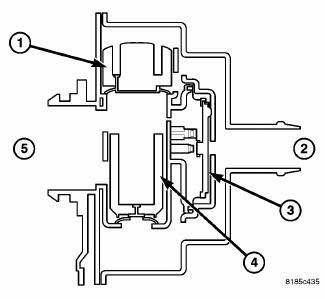
Fig. 31: CUT AWAY OF MODULE
- - Large Check Valve
- - Fresh Air Inlet
- - Diagram
- - Small Check Valve
- - Vapor Canister
The ESIM (Evaporative System Integrity Monitor), while physically different than the NVLD system, performs the same basic function as the NVLD does - controlling evaporative emissions. The ESIM has been simplified because the solenoid used on the NVLD is not used on the ESIM.
The ESIM consists of housing, two check valves (sometimes referred to as weights), a diaphragm, a switch and a cover. The larger check valve seals for pressure and the smaller one seals for vacuum.
During refueling, pressure is built up in the evaporative system. When pressure reaches approximately.5 inches of water, the large check valve unseats and pressure vents to the fresh air filter.
Conversely, when the system cools and the resulting vacuum lifts the small check valve from its seat and allows fresh air to enter the system and relieve the vacuum condition. When a calibrated amount of vacuum is achieved in the evaporative system, the diaphragm is pulled inward, pushing on the spring and closing the contacts.
The ESIM conducts test on the evaporative system as follows: An engine off, non-intrusive test for small leaks and an engine running, intrusive test for medium/large leaks.
The ESIM weights seal the EVAP system during engine off conditions. If the EVAP system is sealed, it will be pulled into a vacuum, either due to the cool down from operating temperature or diurnal ambient temperature cycling. When the vacuum in the system exceeds about 1" H20, the vacuum switch closes. The switch closure sends a signal to the powertrain control module (PCM). In order to pass the non-intrusive small leak test, the ESIM switch must close within a calculated amount of time and within a specified amount of key-off events.
If the ESIM switch does not close as specified, the test is considered inconclusive and the intrusive engine running test will be run during the next key-on cycle. This intrusive test will run on the next cold engine running condition.
Conditions for running the intrusive test are:
- After the vehicle is started, the engine coolant temperature must be within 10º C (50ºF) of ambient to indicate a cold start.
- The fuel level must be between 12% and 88%.
- The engine must be in closed loop.
- Manifold vacuum must be greater than a minimum specified value.
- Ambient temperature must be between 4º C and 37º C (39º F and 98º F) and the elevation level must be below 8500 feet.
The test is accomplished by the PCM activating the purge solenoid to create a vacuum in the evaporative system. The PCM then measures the amount of time it takes for the vacuum to dissipate. This is known as the vacuum decay method. If the switch opens quickly a large leak is recorded. If the switch opens after a predetermined amount of time, then the small leak matures. If the switch does not close, then a general evaporative failure is recorded.
Even when all of the thresholds are met, a small leak won't be recorded until after the medium/large leak monitor has been run. If the medium/large leak test runs and the ESIM switch doesn't close, a general evaporative test is run. The purge solenoid is activated for approximately 10 seconds, increasing the amount of vacuum in the system. IF the ESIM switch closes after the extended purge activation, a large leak fault is generated. If the switch doesn't close, a general evaporative system fault is generated.
The purge monitor tests the integrity of the hose attached between the purge valve and throttle body/intake. The purge monitor is a two stage test and it runs only after the evaporative system passes the small leak test.
Stage one of the purge monitor is non-intrusive. The PCM monitors the purge vapor ratio. If the ratio is above a calibrated specification, the monitor passes. Stage two is an intrusive test and it runs only if stage one fails.
During the stage two test, the PCM commands the purge solenoid to flow at a specified rate to force the purge vapor ratio to update. The vapor ratio is compared to a calibrated specification and if it is less than specified, a one-trip failure is recorded.
The ESIM switch stuck closed monitor checks to see if the switch is stuck closed. This is a power down test that runs at key-off; when the PCM sees 0 rpm's, the purge solenoid is energized for a maximum of 30 seconds, venting any vacuum trapped in the evaporative system. If the switch opens or was open before the test began, the monitor passes. If the switch doesn't open, the monitor fails. This is a two-trip MIL. The star scan tool can be used to force the ESIM switch stuck closed monitor to run.
The PCM also uses the ESIM to detect a loose or missing gas cap. The PCM looks for a change in the fuel level (25% minimum). If a medium/large leak is then detected, a loose gas cap light illuminates and a pending onetrip fault code is set. This is a three-trip fault before the code matures.
Removal
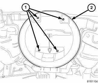
Fig. 32: Spare Tire Well
- - Nuts
- - Spare Tire Well
1. Disconnect and isolate negative battery cable.
2. Remove the spare tire.
3. Raise and support vehicle.
4. Remove the 4 nuts (1) and the spare tire well (2).
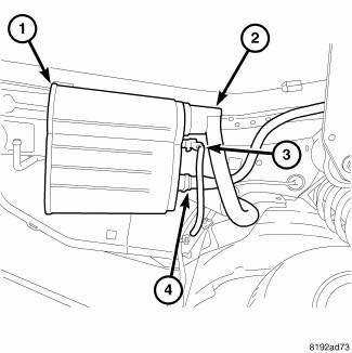
Fig. 33: Canister Mounting Evaporative System Integrity Monitor
5. Remove fresh air hose (2) and electrical connector (3) from the ESIM.
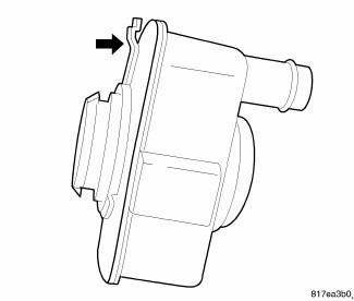
Fig. 34: Natural Vacuum Leak Detection Locking Tab
6. A lock tab (see arrow) is used on the back of the switch. Push lock tab towards switch while rotating switch counterclockwise 1/4 turn for removal.
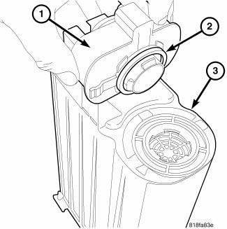
Fig. 35: Evaporative System Integrity Monitor Switch Removed
7. Remove ESIM (1) from the EVAP canister (3).
Installation
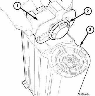
Fig. 36: Evaporative System Integrity Monitor Switch Removed
The picture displays a typical EVAP Canister and a typical ESIM switch. After installing any ESIM switch, the electrical connector on the switch must be in the 3 O'clock position. This step must be done for proper ESIM switch operation.
1. The fresh air hose that attaches to the ESIM must have a clear opening to the atmosphere. Check the fresh air hose, including the fresh air filter, for obstructions or restrictions at the ESIM. If a restriction is present, the system will not allow free flow passage of clean air, and an early shut off of the fuel fill nozzle may occur during fuel fill.
2. Be sure O-ring (2) and EVAP canister opening are clean.
3. Install ESIM (1) to the EVAP canister (3).
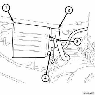
Fig. 37: Canister Mounting Evaporative System Integrity Monitor
4. Install fresh air hose (2) and electrical connector (3) to the ESIM.
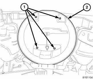
Fig. 38: Spare Tire Well
- - Nuts
- - Spare Tire Well
 Solenoid, evaporative emissions purge
Operation
During the cold start warm-up period and the hot start time delay, the PCM
does not energize the solenoid.
When de-energized, no vapors are purged.
The proportional purge solenoid o ...
 Valve, positive crankcase ventilation (PCV)
Description
The PCV valve contains a spring loaded plunger. The plunger meters the amount
of crankcase vapors routed
into the combustion chamber based on intake manifold vacuum.
Operation
Fig. ...
See also:
Lamp, fog, front
REMOVAL
BULB
CAUTION: Do not contaminate the bulb glass by touching it with
your fingers or by
allowing it to contact other oily surfaces. Shortened bulb life will
result.
...
Speaker
OPERATION
Two wires connected to each speaker, one feed circuit (+) and one return
circuit (-), allow the audio output signal electrical current to flow through
the voice coil. The wiring informa ...
BRAKE SYSTEM
Your vehicle is equipped with dual hydraulic
brake systems. If either of the two hydraulic
systems loses normal capability, the remaining
system will still function. However, there will
be some ...
