Dodge Journey: Tube, air pump, inlet
Description
The air pump inlet tube is located on the left side of the engine compartment. The tube attaches to the air injection pump using a quick connect style fitting. The other end of the tube connects to the mass air flow sensor using a constant tension clamp.
Removal

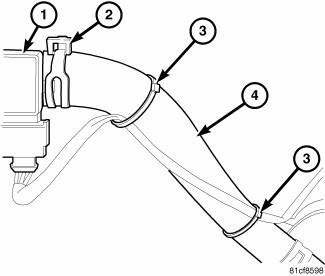
Fig. 12: Air Inlet Tube At Mass Air Flow
1. Cut the tie straps (3) being careful not to damage the air inlet tube (4).
2. Remove the constant tension clamp (2) and remove the mass air flow (MAF) sensor (1) from the air inlet tube (4). Position MAF sensor (1) and wiring aside.

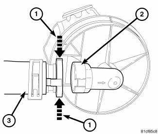
Fig. 13: AIR INLET TUBE AT AIR PUMP
3. Remove air inlet tube (3) by pushing the ends (1) together, while pulling the air inlet tube (3) away from air pump housing connection (2).
Installation

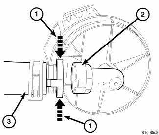
Fig. 14: AIR INLET TUBE AT AIR PUMP
NOTE: The quick connect fitting on the air inlet tube is slotted to fit the air pump housing fitting. Line the slot up when making the connection.
1. Install air inlet tube (3) to air pump housing connection (2). A click noise will indicate a good connection.

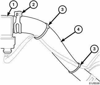
Fig. 15: Air Inlet Tube At Mass Air Flow
2. Install mass air flow (MAF) sensor (1) and constant tension clamp (2) to air inlet tube (4).
3. Position MAF sensor wiring to air inlet tube (4). Install new tie straps (3) securing the MAF sensor wiring to air inlet tube (4).
 Sensor, mass air flow (MAF)
Removal
Fig. 10: MASS AIR FLOW SENSOR
1. Disconnect air flow sensor electrical connector (4).
2. Remove constant tension clamps (1), (2) securing the air flow sensor (3).
3. Remove air flow ...
 Valve, one way check
Description
Fig. 16: AIR INJECTION CHECK VALVE
The air injection check valve (1) is a one-valve check valve that allows air
to flow in one direction only. The
valve is located at exhaust side o ...
See also:
Cooler and lines, oil
Description
Fig. 250: Oil Cooler Fasteners
Some 2.7L engines may be equipped with an engine oil cooler (2) that is
mounted to the rear transmission
mount bracket. Oil lines route oil from the e ...
Removal, Installation
REMOVAL
WARNING: To protect the hands from battery acid, a suitable pair
of heavy duty
rubber gloves should be worn when removing or servicing a battery.
Safety glasses also should ...
Description, Operation
DESCRIPTION
Fig. 238: Evaporator Description
NOTE: LHD model shown. RHD model similar.
The A/C evaporator (1) for the heating-A/C system is mounted in the HVAC
housing, which is located be ...
