Dodge Journey: Radiator, engine cooling
Description
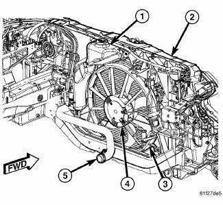
Fig. 99: COOLING SYSTEM - OVERVIEW
- - WINDSHIELD WASHER RESERVOIR
- - UPPER SUPPORT
- - FAN SHROUD
- - FAN MOTOR
- - LOWER RADIATOR HOSE
All vehicles are equipped with a cross flow type radiator with plastic side tanks.
Plastic tanks, while stronger than brass, are subject to damage by impact, such as from tools or wrenches.
Handle radiator with care.
Removal
RADIATOR
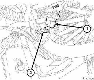
Fig. 100: UPPER RADIATOR HOSE
- - ELECTRICAL CONNECTOR
- - UPPER RADIATOR HOSE
1. Disconnect negative cable from auxiliary jumper terminal.
2. Remove engine cover.
3. Remove air box assembly.
4. Recover A/C system.
WARNING: Do not remove pressure cap or any hose with the system hot and under pressure because serious burns from coolant can occur.
5. Drain cooling system.
6. Remove the grille.
7. Remove under belly pan (if equipped).
8. Remove front bottom splash shield (if equipped).
9. Remove upper and lower radiator hoses at radiator.
10. Disconnect radiator fan electrical connector (1).
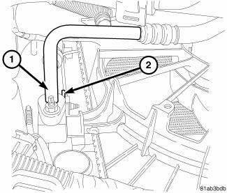
Fig. 101: A/C LINE
- - A/C LINE
- - SUPPORT BRACKET
11. Separate radiator cooling fans from radiator.
12. Disconnect A/C line (1) at condenser/cooler.
13. Remove transmission oil cooler tubes support bracket at left side of radiator (if equipped) (2).
CAUTION: Plastic tanks, while stronger than brass are subject to damage by impact, such as wrenches.
14. Remove the two torx screws located on the upper radiator support that hold the upper radiator mounting brackets.
15. Tilt the top of the radiator rearward so the mounting brackets slide out of the upper core support.
16. Remove radiator/condenser assembly by lifting the assembly out of the vehicle between the engine and the core support.
17. Separate the A/C condenser from the radiator.
Cleaning
Clean radiator fins are necessary for good heat transfer. The radiator and air conditioning fins should be cleaned when an accumulation of debris has occurred. With the engine cold, apply cold water and compressed air to the back (engine side) of the radiator to flush the radiator and/or A/C condenser of debris.
Inspection
Inspect the radiator tanks for cracks, broken or missing fittings also inspect the joint where the tanks seam up to the radiator core for signs of leakage and/or deteriorating seals.
Inspect radiator core for corroded, bent or missing cooling fins. Inspect the core for bent or damaged cooling tubes.
Installation
RADIATOR
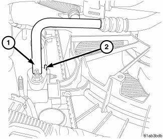
Fig. 102: A/C LINE
- - A/C LINE
- - SUPPORT BRACKET
1. Position radiator cooling fans on radiator.
2. Position combination A/C condenser/cooler on radiator.
3. Slide radiator into position and seat the radiator assembly lower rubber isolators in the mount holes.
4. Install A/C lines (1) to condenser.
5. Install support bracket (2) to radiator. Tighten mounting screws to 5 N.m (45 in. lbs.).
6. Connect cooling fan electrical connector (1).
7. Install lower radiator hose at radiator.
8. Install upper radiator mount.
9. Install front bottom splash shield
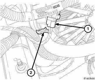
Fig. 103: UPPER RADIATOR HOSE
- - ELECTRICAL CONNECTOR
- - UPPER RADIATOR HOSE
10. Install under engine splash shield.
11. Fill cooling system.
12. Charge A/C system.
13. Install air filter housing.
14. Install engine cover.
15. Install transmission oil cooler tube support bracket and attaching screw to left side of radiator. Tighten mounting screw to 5 N.m (45 in. lbs.).
16. Connect hoses to radiator.
17. Install radiator fan.
18. Connect radiator fan electrical connector.
19. Connect negative cable.
 Pump, water
Description
2.4L
Fig. 80: WATER PUMP - WORLD ENGINE
- ACCESSORY DRIVE BELT
- WATER PUMP PULLEY
- WATER PUMP
The water pump (3) on the world engine is attached to the water pump adapter ...
 Sensor, coolant temperature
Description
There are two Engine Coolant Temperature (ECT) Sensors. One of the sensors
threads into the block. The other
sensor is located at the top of the coolant adapter housing. The ECT Sensor ...
See also:
Disassembly
NOTE: The strut assembly must be removed from the vehicle for it to be
disassembled
and assembled.
For the disassembly and assembly of the strut assembly, use strut spring
compressor, tea ...
Disassembly
Fig. 241: Tapping Down Reverse Clutch Reaction Plate
- #4 THRUST PLATE (SELECT)
- TAP DOWN REVERSE CLUTCH REACTION PLATE TO REMOVE OR INSTALL SNAP RING
- INPUT SHAFT CLUTCHES RETAINER ASSEMB ...
Switch, hazard warning
DESCRIPTION
Fig. 44: Instrument Panel Switch Pod
The hazard switch (3) is integral to the instrument panel switch pod (1),
which is secured to the instrument
panel center bezel just above the h ...
