Dodge Journey: Heater, engine block
Description
2.4L

Fig. 70: BLOCK HEATER 2.4L ENGINE
- - RETAINING CLIP
- - BLOCK HEATER
CAUTION: The power cord must be secured in its retainer clips, and not positioned so it could contact linkages or exhaust manifolds and become damaged.
The block heater is operated by ordinary house current (110 Volt A.C.) through a power cord and connector located in the engine compartment. The heater is mounted in a bore in the engine block and held in place by a retaining clip.
2.7L
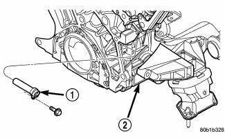
Fig. 71: ENGINE BLOCK HEATER
- - BLOCK HEATER
- - ENGINE - RIGHT SIDE
The engine block heater is mounted in the cylinder block, near the right rear corner. The block heater is a dry cylinder type design and is powered by 110 volt AC. The power cord must be secured in its retainer clips, and not positioned so it could contact linkages or exhaust manifolds and become damaged.
Operation
When power is applied (110 volt A.C.) to the block heater, the heating element transfers heat through the aluminum engine block and into the coolant without directly penetrating the cooling system.
Diagnosis and Testing
ENGINE BLOCK HEATER TESTING
If unit does not operate, test power cord for continuity with a 110-volt voltmeter or 110-volt test light. Test heater element continuity with an ohmmeter or 12-volt test light.
Removal
2.4L

Fig. 72: BLOCK HEATER 2.4L ENGINE
- - RETAINING CLIP
- - BLOCK HEATER
1. Detach power cord plug from block heater.
2. Unclip retainer clip. Remove block heater assembly.
2.7L

Fig. 73: ENGINE BLOCK HEATER
- - BLOCK HEATER
- - ENGINE - RIGHT SIDE
1. Raise vehicle on hoist.
2. Detach power cord plug from heater.
3. Remove block heater attaching screw located below heater terminals.
4. Remove block heater from cylinder block.
3.5L

Fig. 74: Engine Block Heater
- - BLOCK HEATER
- - ENGINE - RIGHT SIDE
1. Raise vehicle on hoist.
2. Detach power cord plug from heater.
3. Remove block heater attaching screw located below heater terminals.
4. Remove block heater from cylinder block.
Installation
2.4L
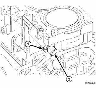
Fig. 75: BLOCK HEATER 2.4L ENGINE
- - RETAINING CLIP
- - BLOCK HEATER
CAUTION: To prevent damage, the power cord must be secured in it's retaining clips, and not positioned so it could contact linkages or exhaust manifold.
1. Thoroughly clean block heater bore.
2. Insert block heater assembly. Make sure retaining clip engages on cylinder block.
3. Connect power cord to heater.
4. Lower vehicle.
2.7L

Fig. 76: ENGINE BLOCK HEATER
- - BLOCK HEATER
- - ENGINE - RIGHT SIDE
1. Thoroughly clean cylinder block heater cavity.
2. Insert heater assembly into block such that mounting hole is located below heater terminals.
3. Install mounting screw and tighten to 12 N.m (105 in. lb.).
CAUTION: To prevent damage, the power cord must be secured in its retainer clips, and not positioned so it could contact linkages or exhaust manifolds.
4. Attach power cord to heater.
5. Lower vehicle.
3.5L

Fig. 77: ENGINE BLOCK HEATER
- - BLOCK HEATER
- - ENGINE - RIGHT SIDE
1. Thoroughly clean cylinder block heater cavity.
2. Insert heater assembly into block such that mounting hole is located below heater terminals.
3. Install mounting screw and tighten to 12 N.m (105 in. lb.).
CAUTION: To prevent damage, the power cord must be secured in its retainer clips, and not positioned so it could contact linkages or exhaust manifolds.
4. Attach power cord to heater.
5. Lower vehicle.
 Fan, cooling
Description
Fig. 67: COOLING SYSTEM - OVERVIEW
- WINDSHIELD WASHER RESERVOIR
- UPPER SUPPORT
- FAN SHROUD
- FAN MOTOR
- LOWER RADIATOR HOSE
The radiator fan module includes a support ...
 Housing, coolant outlet
Removal
Fig. 78: COOLANT OUTLET CONNECTOR - 2.7L
- BOLT (2)
- BOLT (2)
- COOLANT OUTLET CONNECTOR
WARNING: Do not remove pressure cap with the system hot and under
pressure
...
See also:
Description, Operation
DESCRIPTION
Fig. 1: Battery Components
This vehicle is equipped with a single 12-volt battery. All of the components
of the battery system are located in
the front of the vehicle, just ahead of ...
Removal
1. Raise and support the vehicle.
NOTE: Perform 2 through 5 on each side of the vehicle to complete pad
set
removal.
Fig. 117: TIRE AND WHEEL MOUNTING
2. Remove the wheel mounting nuts ...
Actuator, blend door, rear
DESCRIPTION
Fig. 47: Rear Actuator Description
The blend door actuator (1) for the rear heating-A/C system is a reversible,
12 volt direct current (DC), servo
motor. The rear blend door actuato ...
