Dodge Journey: Fan, cooling
Description

Fig. 67: COOLING SYSTEM - OVERVIEW
- - WINDSHIELD WASHER RESERVOIR
- - UPPER SUPPORT
- - FAN SHROUD
- - FAN MOTOR
- - LOWER RADIATOR HOSE
The radiator fan module includes a support shroud (2) with an electrically driven motor (1) with a fan blade.
The radiator fan module is attached to the radiator.
Operation
The radiator fans are controlled by the Powertrain Control Module (PCM) which energizes a high speed or low speed fan relay. The electric motor drives the cooling fan to produce air flow across the radiator fins.
Diagnosis and Testing
RADIATOR FAN CONTROL
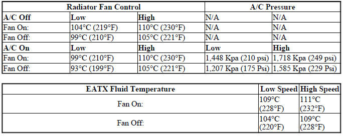
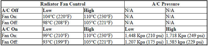
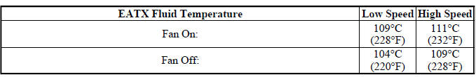
Fan control is accomplished three ways. The fan runs when the air conditioning pressure reaches a set pressure, refer to RADIATOR FAN OPERATION charts. In addition to this control, the fan is turned on by the temperature of the coolant which is sensed by the coolant temperature sensor which sends the message to the Powertrain Control Module (PCM). The PCM turns on the fan through a fan relay. On models equipped with automatic transmission, a transmission fluid thermistor may have some influences on fan operation.
The Powertrain Control Module (PCM) provides fan control for the following conditions:
- The fan will not run during cranking until the engine starts no matter what the coolant temperature is.
- Fan will run when the air conditioning clutch is engaged, and once set compressor head pressure is reached. See charts.
- Fan will run according to the following information charts.
RADIATOR FAN OPERATION - 2.4L ENGINE
RADIATOR FAN OPERATION - 3.5L ENGINE
ELECTRIC FAN MOTOR TEST
Refer to the appropriate Diagnostic Service Information for testing the fan motor with the scan tool.
For wiring diagrams of the fan motor systems refer to WIRING HARNESS - SERVICE INFORMATION .
Removal
REMOVAL
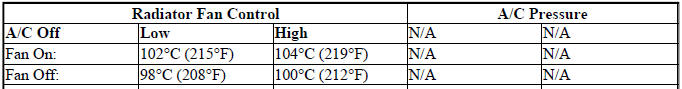
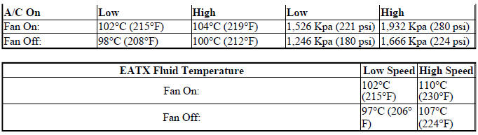
Fig. 68: COOLING SYSTEM - OVERVIEW
- - WINDSHIELD WASHER RESERVOIR
- - UPPER SUPPORT
- - FAN SHROUD
- - FAN MOTOR
- - LOWER RADIATOR HOSE
1. Disconnect and isolate negative battery cable.
2. Remove windshield washer reservoir.
3. Drain cooling system below level of the upper radiator hose.
4. Remove upper radiator hose at radiator and position aside.
5. Disconnect radiator fan electrical connector.
6. Remove fasteners and un-clip radiator fan assembly from radiator.
7. Remove radiator fan assembly by lifting upward.
Inspection
Inspect fan blades for damage. If the fan blades are warped, cracked, or otherwise damaged, it must be replaced with only the recommended replacement part for adequate strength, performance and safety.
Check fan motor operation. If fan motor is inoperative, and the fan blades are not damaged, the fan motor can be replaced separately.
Installation

Fig. 69: COOLING SYSTEM - OVERVIEW
- - WINDSHIELD WASHER RESERVOIR
- - UPPER SUPPORT
- - FAN SHROUD
- - FAN MOTOR
- - LOWER RADIATOR HOSE
1. Position radiator fan into retaining clips.
2. Install mounting bolts. Tighten bolts to 35 N.m (25 ft. lbs.)
3. Connect radiator fan electrical connector.
4. Install windshield washer reservoir.
5. Install upper radiator hose at radiator.
6. Fill cooling system.
7. Connect negative battery cable.
 Draincock, radiator
Removal
DRAINCOCK
Fig. 65: DRAINCOCK & RADIATOR TANK
CAUTION: Use of pliers on draincock is not recommended. Damage may
occur to
radiator or draincock.
NOTE: It is no ...
 Heater, engine block
Description
2.4L
Fig. 70: BLOCK HEATER 2.4L ENGINE
- RETAINING CLIP
- BLOCK HEATER
CAUTION: The power cord must be secured in its retainer clips, and
not positioned
so it co ...
See also:
Resistor, blower motor, rear
DESCRIPTION
Fig. 62: Rear Blower Resistor
A blower motor resistor is used on this model when equipped with the manual
temperature control (MTC) rear
heating-A/C system. Models equipped with the ...
Removal, Installation
REMOVAL
WARNING: Disable the airbag system before attempting any steering
wheel, steering
column or instrument panel component diagnosis or service. Disconnect
and isolate the negati ...
Description, Operation, Diagnosis and Testing
DESCRIPTION
The lubrication system is a full-flow filtration, pressure feed type. The oil
pump body is mounted to the engine
block. The pump inner rotor is driven by the crankshaft. A structural w ...
