Dodge Journey: Cooler, EGR
Description
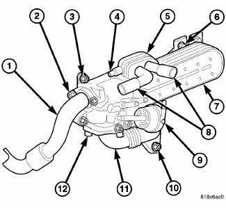
Fig. 62: EGR COOLER
- - EGR COOLER TO EGR VALVE TUBE
- - MOUNTING SCREWS
- - EGR COOLER MOUNTING SCREW
- - MOUNTING SCREW
- - EGR COOLER BODY
- - EGR COOLER MOUNTING NUT
- - EGR COOLER
- - INLET TUBES
- - VACUUM CONTROL UNIT
- - EGR COOLER TO EXHAUST MANIFOLD TUBE MOUNTING NUT
- - EGR COOLER TO EXHAUST MANIFOLD TUBE
- - MOUNTING SCREW
The EGR cooler (7) cools recirculated exhaust gasses to reduce combustion temperature and a greater mass of exhaust gases can thus be circulated. There is less nitrogen oxides as a result.
The EGR cooler (7) allows the engine and catalytic converter to reach their operating temperature quickly.
Removal

Fig. 63: EGR COOLER
- - EGR COOLER TO EGR VALVE TUBE
- - MOUNTING SCREWS
- - EGR COOLER MOUNTING SCREW
- - MOUNTING SCREW
- - EGR COOLER BODY
- - EGR COOLER MOUNTING NUT
- - EGR COOLER
- - INLET TUBES
- - VACUUM CONTROL UNIT
- - EGR COOLER TO EXHAUST MANIFOLD TUBE MOUNTING NUT
- - EGR COOLER TO EXHAUST MANIFOLD TUBE
- - MOUNTING SCREW
1. Remove engine cover.
2. Drain cooling system.
3. Remove EGR cooler coolant hoses (8).
4. Remove EGR cooler to exhaust manifold tube (11).
5. Remove EGR cooler to EGR valve tube (1).
6. Remove EGR cooler mounting nuts (6).
7. Remove EGR cooler (7).
8. Remove the bypass valve mounting screws (3).
9. Separate the bypass valve assembly from the EGR cooler body (5).
Installation

Fig. 64: EGR COOLER
- - EGR COOLER TO EGR VALVE TUBE
- - MOUNTING SCREWS
- - EGR COOLER MOUNTING SCREW
- - MOUNTING SCREW
- - EGR COOLER BODY
- - EGR COOLER MOUNTING NUT
- - EGR COOLER
- - INLET TUBES
- - VACUUM CONTROL UNIT
- - EGR COOLER TO EXHAUST MANIFOLD TUBE MOUNTING NUT
- - EGR COOLER TO EXHAUST MANIFOLD TUBE
- - MOUNTING SCREW
1. Using a new gasket, position the bypass valve assembly to the EGR cooler body (5). Tighten screws to 10 N.m (88 in. lbs.).
2. Position EGR cooler (7) and install mounting screws. Tighten to 10 N.m (88 in. lbs.).
3. Install EGR cooler to exhaust manifold tube (11). Tighten bolts to 20 N.m (14 ft. lbs.) and nuts to 20 N.m (14 ft. lbs.).
4. Install EGR cooler to EGR valve tube (1). Tighten bolts to 20 N.m (14 ft. lbs.).
5. Install coolant hoses.
6. Install vacuum line.
7. Fill cooling system.
8. Install engine cover.
 Coolant
Description
ENGINE COOLANT
GAS ENGINES
WARNING: Antifreeze is an ethylene glycol based coolant and is
harmful if swallowed
or inhaled. If swallowed, drink two glasses of water and ind ...
 Draincock, radiator
Removal
DRAINCOCK
Fig. 65: DRAINCOCK & RADIATOR TANK
CAUTION: Use of pliers on draincock is not recommended. Damage may
occur to
radiator or draincock.
NOTE: It is no ...
See also:
With intermediate shaft
NOTE: The inner tripod joints are designed with a retention feature
that prevents the
tripod rollers from coming out of the inner joint housing up to a specific
load. If
this feature is o ...
VEHICLE LOADING
The load carrying capacity of your vehicle is shown on
the “Vehicle Certification Label.” This information
should be used for passenger and luggage loading as
indicated.
Do not exceed the spec ...
Knob, gearshift
REMOVAL
Fig. 357: Removing/Installing Gearshift Knob
1. Loosen the set screw (3) on the shift knob (2).
2. Hold in the shift knob button (1).
3. Pull up on the shift knob (2) while holding t ...
