Dodge Journey: Pulley, idler
Removal
2.4L ENGINE
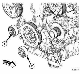
Fig. 30: ACCESSORY DRIVE BELT IDLER PULLEY - 2.4L
- - UPPER PULLEY
- - LOWER PULLEY
1. Remove accessory drive belt.
2. Remove upper idler pulley (1) and bolt.
3. Remove lower idler pulley (2) and bolt.
3.5L ENGINE
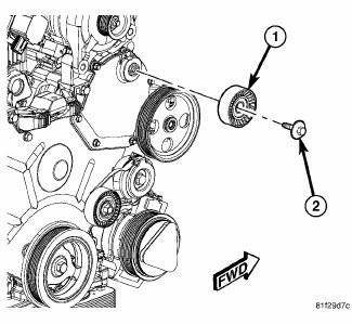
Fig. 31: IDLER PULLEY - 3.5L
- - IDLER PULLEY
- - BOLT
1. Remove accessory drive belt.
2. Remove mounting bolt (2) and idler pulley (1).
2.0L DIESEL ENGINE
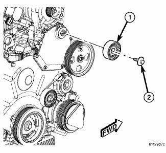
Fig. 32: IDLER PULLEY - 2.0L DIESEL
- - IDLER PULLEY
- - DUST SHIELD
- - CAP
- - BOLT
1. Remove accessory drive belt.
2. Remove bolt (4), cap (3), idler pulley (1), and dust shield (2).
Installation
2.4L ENGINE
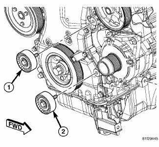
Fig. 33: ACCESSORY DRIVE BELT IDLER PULLEY - 2.4L
- - UPPER PULLEY
- - LOWER PULLEY
1. Position lower idler pulley (2) and bolt.
2. Tighten bolt to 35 N.m (25 ft. lbs.).
3. Position upper idler pulley (1) and bolt.
4. Tighten bolt to 35 N.m (25 ft. lbs.).
5. Install accessory drive belt. See Installation .
3.5L ENGINE
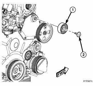
Fig. 34: IDLER PULLEY - 3.5L
- - IDLER PULLEY
- - BOLT
1. Position idler pulley and bolt.
2. Tighten bolt to 35 N.m (25 ft. lbs.).
3. Install accessory drive belt.
2.0L DIESEL ENGINE
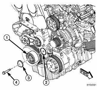
Fig. 35: IDLER PULLEY - 2.0L DIESEL
- - IDLER PULLEY
- - DUST SHIELD
- - CAP
- - BOLT
1. Position bolt (4), cap (3), idler pulley (1) and dust shield (2) on front engine cover.
2. Tighten bolt to 35 N.m (25 ft.lbs.).
3. Install accessory drive belt.
 Belt, serpentine, power steering
Removal
2.7L ENGINE
Fig. 28: STRETCH TO FIT POWER STEERING BELT REMOVAL
- POWER STEERING PULLEY
- STRETCH TO FIT POWER STEERING BELT
1. Raise and support the vehicle.
2. Remove RH whee ...
 Ensioner, belt
Removal
2.4L ENGINE
Fig. 36: ACCESSORY DRIVE BELT - WORLD ENGINE
- POWER STEERING PUMP
- ACCESSORY DRIVE BELT
- GENERATOR
- CRANKSHAFT PULLEY
- LOWER IDLER PULLEY
- CRANKSHAFT PULLEY ...
See also:
Diagnosis and Testing
PARK BRAKE SWITCH
WARNING: To avoid serious or fatal injury on vehicles equipped
with airbags, disable
the Supplemental Restraint System (SRS) before attempting any steering
wheel, s ...
Fluid
STANDARD PROCEDURE
FLUID LEVEL CHECKING
The fluid required for this transaxle is Mopar ATF+4 (Automatic Transmission
Fluid). Use of improper or
substitute fluids can cause shift problems and/or t ...
Valve, one way check
Description
Fig. 16: AIR INJECTION CHECK VALVE
The air injection check valve (1) is a one-valve check valve that allows air
to flow in one direction only. The
valve is located at exhaust side o ...
