
Dodge Journey: Description, Operation
DESCRIPTION
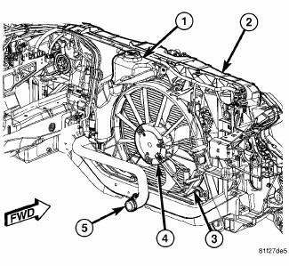
Fig. 1: COOLING SYSTEM - OVERVIEW
- - WINDSHIELD WASHER RESERVOIR
- - UPPER SUPPORT
- - FAN SHROUD
- - FAN MOTOR
- - LOWER RADIATOR HOSE
The cooling system consists of an engine cooling module, thermostat, non-pressure coolant recovery container on the 2.4L engine, or pressurized coolant recovery container on the 2.7L, 3.5L, and 2.0L Diesel engines, coolant, hoses, and a water pump to circulate the coolant. The engine cooling module consists of a radiator, electric fan, shroud, transmission oil cooler, and air conditioning condenser.
OPERATION
GAS ENGINE
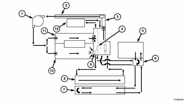
Fig. 2: COOLING SYSTEM FLOW - 2.4L
- - WATER PUMP
- - RETURN TUBE
- - WATER PLENUM
- - PRIMARY THERMOSTAT
- - TRANSMISSION
- - INTERNAL TRANSMISSION COOLER
- - COMBINATION COOLER
- - RADIATOR
- - SECONDARY THERMOSTAT
- - CYLINDER BLOCK
- - CYLINDER HEAD
- - HEATER CORE
The primary purpose of a cooling system is to maintain engine temperature in a range that will provide satisfactory engine performance and emission levels under all expected driving conditions.
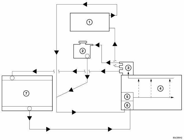
Fig. 3: Cooling System Operation - 2.7L
- - HEATER CORE
- - COOLANT PRESSURE CONTAINER
- - COOLANT OUTLET CONNECTOR
- - ENGINE
- - WATER PUMP
- - THERMOSTAT
- - RADIATOR
The cooling system also provides hot water (coolant) for heater performance.
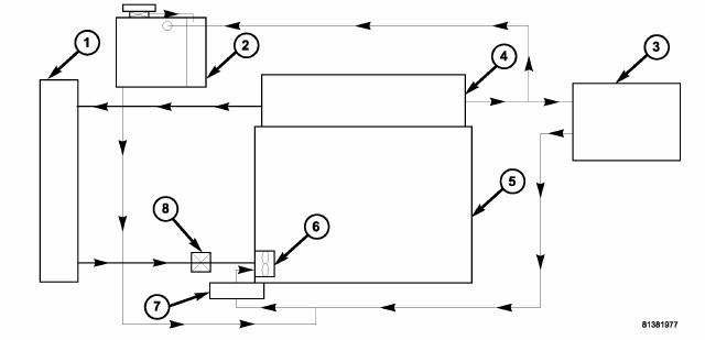
Fig. 4: COOLING FLOW - 3.5L W/ENGINE OIL COOLER ENGINE
- - RADIATOR
- - HOT BOTTLE/COOLANT RECOVERY BOTTLE
- - HEATER CORE
- - CYLINDER HEAD
- - CYLINDER BLOCK
- - WATER PUMP
- - ENGINE OIL COOLER
- - THERMOSTAT
DIESEL ENGINE
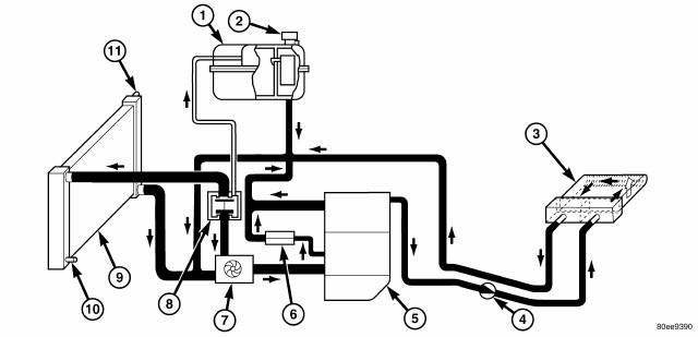
Fig. 5: COOLING SYSTEM FLOW
- - COOLANT RECOVERY PRESSURE CONTAINER
- - PRESSURE CAP
- - HEATER CORE
- - AUXILIARY HEATER
- - ENGINE
- - OIL COOLER
- - WATER PUMP
- - THERMOSTAT HOUSING
- - RADIATOR
- - COOLANT DRAIN VALVE
- - SERVICE FILL VENT VALVE
The water pump draws coolant from the radiator and delivers it to the engine block. The coolant travels through the engine block into the cylinder head. Coolant exits the engine at the thermostat. If the coolant temperature is less than 87ºC (189ºF) the thermostat directs all of the coolant back to the water pump. If the coolant temperature is between 87ºC (189ºF) and 102ºC (216ºF) the thermostat is in the mix mode and directs the coolant to the radiator and the water pump. If the coolant is greater than 102ºC (216ºF), the thermostat directs all of the coolant to the radiator.
The thermostat also feeds excess coolant and bleeds air from the system through a hose leading to the coolant reservoir. The reservoir returns coolant to the inlet side of the water pump. A port and hose at the rear of the engine block provides coolant to the heater core. This coolant is returned to the engine at the intake side of the water pump.
The oil cooler receives coolant directly from the engine block. A hose returns this coolant to the inlet side of the water pump.
 Cooling
...

See also:
CARGO AREA FEATURES
Rechargeable Flashlight — If Equipped
The rechargeable LED flashlight stores in its charging
station in the left rear quarter trim panel. To remove it,
press on the indent on the side of the flas ...
POWER SUNROOF — IF EQUIPPED
The power sunroof switch is located between the sun
visors on the overhead console.
Power sunroof Switch
WARNING:
• Never leave children in a vehicle with the key in
the ignition switch. Occu ...
MEDIA CENTER 230 (REQ) — AM/FM STEREO RADIO AND 6–DISC CD/DVD CHANGER
(MP3/WMA AUX JACK)
NOTE: The radio sales code is located on the lower right
side of the radio faceplate.
REQ Radio
Operating Instructions - Radio Mode
NOTE: The ignition switch must be in the ON or ACC
position t ...
