Dodge Journey: Manifold, intake
Diagnosis and Testing
INTAKE MANIFOLD LEAKS
An intake manifold air leak is characterized by lower than normal manifold vacuum. Also, one or more cylinders may not be functioning.
WARNING: Use extreme caution when the engine is operating. Do not stand in a direct line with the fan. Do not put your hands near the pulleys, belts or the fan. Do not wear loose clothing.
1. Start the engine.
2. Spray a small stream of water (Spray Bottle) at the suspected leak area.
3. If engine RPM'S change, the area of the suspected leak has been found.
4. Repair as required.
Standard Procedure
INTAKE MANIFOLD VACUUM PORT REPAIR
Fig. 317: MANIFOLD PORT (NIPPLE) REPAIR
- - 1/4" - 18 NPT PIPE TAP
- - NIPPLE (PORT)
The composite intake manifold vacuum ports can be repaired. Although, if the manifold plenum chamber is damaged or cracked, the manifold must be replaced.
To repair a broken or damaged vacuum nipple (port) on the composite intake manifold, perform the following procedure:
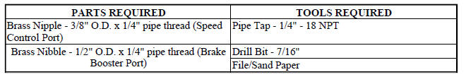
NOTE: While performing this procedure, avoid getting the manifold material residue into the plenum chamber.
1. File or sand the remaining port back until a flat surface is obtained (plane normal to nipple (port) axis).
2. Drill out the nipple (port) base using a 7/16" drill bit.
3. Using a 1/4"-18 NPT pipe tap, cut internal threads. Use caution to start tap in a axis same as original nipple.
4. Apply Mopar Thread Sealant to threads of repair nipple(s).
5. Install repair nipple(s). Do not over torque repair nipple(s).
Removal

Fig. 318: Identifying Air Makeup Hose, Throttle Body & Air Inlet Hose
1. Disconnect and isolate the negative battery cable.
2. Remove the throttle body air inlet hose (2) and air cleaner housing assembly.
Fig. 319: Locating Upper Exhaust Gas Recirculation Tube, Brake Booster Hose &
Vapor Purge
Hose
3. Remove the upper EGR tube (3).
4. Disconnect the brake booster hose (1) and the vapor purge hose (2) from the upper intake manifold.
Fig. 320: Intake Brackets
5. Remove the two intake manifold support brackets (1).
Fig. 321: Locating Manifold Bolts, Manifold Absolute Pressure Sensor &
Electronic Throttle
Control Electrical Connectors
6. Disconnect the electrical connectors from the Manifold Absolute Pressure (MAP) sensor (2) and the Electronic Throttle Control (ETC) (3).
7. Disconnect the Positive Crankcase Ventilation (PCV) hose (1).
8. Remove the seven manifold attaching bolts in reverse of the tightening sequence shown in illustration.
9. Remove the upper intake manifold.
LOWER
Fig. 322: Fuel Injector Location - Typical
1. Release fuel system pressure.
2. Remove upper intake manifold. See Engine/Manifolds/MANIFOLD, Intake - Removal.
3. Disconnect electrical connectors from the fuel injectors.
4. Remove fuel supply hose from fuel rail
5. Remove screw attaching fuel rail support bracket to the throttle body support bracket.
6. Remove bolts attaching fuel rail.
Fig. 323: FUEL RAIL REMOVE/INSTALL
7. Remove fuel rail and injectors as an assembly.
Fig. 324: Lower Intake Manifold Tightening Sequence
8. Remove manifold attaching bolts.
9. Remove lower manifold.
10. Inspect manifold.
Inspection
INTAKE MANIFOLD UPPER
Check manifold for:
- Damage and cracks
- Gasket surface damage or warpage
- Damaged or clogged EGR ports
If the manifold exhibits any damaged or warped conditions, replace the manifold. Clean EGR ports as necessary.
If a vacuum port is damaged, a repair procedure can be performed.
INTAKE MANIFOLD LOWER
Check manifold for:
- Damage and cracks
- Gasket surface damage or warpage
- Damaged fuel injector ports
If the manifold exhibits any of these conditions, replace the manifold.
Installation
UPPER

Fig. 325: Locating Manifold Bolts, Manifold Absolute Pressure Sensor &
Electronic Throttle Control
Electrical Connectors
1. Clean and inspect the gasket sealing surfaces. Gaskets can be reused if free of cuts or tears.
NOTE: Make sure the fuel injectors and wiring harnesses are positioned to not interfere with upper manifold installation.
2. Position the upper intake manifold onto the lower intake manifold.
3. Install the manifold attaching bolts and tighten in the sequence shown in illustration to 12 N.m (105 in.lbs.).
4. Connect the Positive Crankcase Ventilation (PCV) hose (1).
5. Connect the electrical connectors to the Manifold Absolute Pressure (MAP) sensor (2) and the Electronic Throttle Control (ETC) (3).

Fig. 326: Locating Upper Exhaust Gas Recirculation Tube, Brake Booster Hose &
Vapor Purge
Hose
6. Connect the brake booster hose (1) and the vapor purge hose (2) to the upper intake manifold.
7. Install the upper EGR tube (3).

Fig. 327: Intake Brackets
8. Install the two intake manifold support brackets (1). Tighten the fasteners to 12 N.m (105 in. lbs.).
Fig. 328: Identifying Air Makeup Hose, Throttle Body & Air Inlet Hose
9. Install the air cleaner housing assembly and connect the throttle body air inlet hose (2). See Engine/Air Intake System/BODY, Air Cleaner - Installation.
10. Connect the negative battery cable and tighten nut to 5 N.m (45 in. lbs.).
LOWER

Fig. 329: Lower Intake Manifold Tightening Sequence
1. Clean and inspect sealing surfaces of cylinder head and manifold. Gaskets can be reused provided they are free of cuts or tears.
2. Position manifold on cylinder head surfaces.
NOTE: For ease of installing upper intake manifold, install a bolt 2 - 3 turns to the rearmost attaching hole of intake. This will properly position lower manifold.
3. Install manifold attaching bolts and tighten in sequence shown in illustration, to 12 N.m (105 in. lbs.).
Remove bolt used for aligning manifold.

Fig. 330: FUEL RAIL REMOVE/INSTALL
4. Install fuel rail with injectors.
5. Connect the fuel injector electrical connectors.
NOTE: Make sure fuel injectors are located in the correct location and position, as upper intake manifold interference could occur.
6. Install screw attaching fuel rail support bracket to the throttle body support bracket.
7. Connect fuel supply hose to fuel rail.
8. Install upper intake manifold.
 Manifold, exhaust, rear
Removal
Fig. 305: Belly Pan
- belly pan fasteners
- belly pan
1. Remove the belly pan (2).
Fig. 306: Oxygen Sensors
2. Remove the oxygen sensors (2) and (4).
Fig. 307: Exhaust Gas R ...
 Valve timing
...
See also:
Adjustments
NOTE: Perform all differential bearing preload measurements with the
transfer shaft
and gear removed.
DIFFERENTIAL BEARING PRELOAD ADJUSTMENT USING EXISTING SHIM
Fig. 348: Installing Too ...
INSTRUMENT PANEL FEATURES
INSTRUMENT PANEL FEATURES
1 — Side Window Demist Outlet.
5 — Hazard Switch.
9 — Climate Control.
2 — Air Outlet.
6 — Switch Bank.
10 — Radio.
3 — Instrument Cluster.
7 — Beve ...
Specifications
2.7L ENGINE
GENERAL SPECIFICATIONS
CYLINDER BLOCK
PISTONS
PISTON PINS
PISTON RINGS
PISTON RING SIDE CLEARANCE
PISTON RING WIDTH
CONNECTING RODS
CRANKSHAFT MA ...
