Dodge Journey: Manifold, exhaust, front
Removal
1. Disconnect negative battery cable.
2. Remove the engine cover.
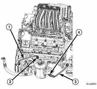
Fig. 295: Oxygen Sensors
3. Disconnect and remove oxygen sensors (2) and (4).
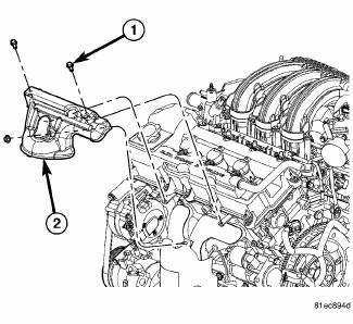
Fig. 296: Upper Maniverter Heat Shield
4. Remove the upper maniverter heat shield (2).
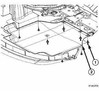
Fig. 297: Belly Pan
- - belly pan fasteners
- - belly pan
5. Remove the belly pan (2).
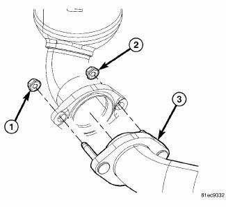
Fig. 298: Front Maniverter-To-Cross Under Fasteners
6. Remove the front maniverter-to-crossunder fasteners (1) and (2).
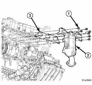
Fig. 299: Front Exhaust Maniverter Attaching Bolts
7. Remove front exhaust maniverter attaching bolts (1) and remove the front maniverter (2).
Inspection
1. Inspect exhaust manifolds for damage or cracks.
2. Check manifold flatness.
3. Inspect the exhaust manifold gasket for obvious discoloration or distortion.
4. Check distortion of the cylinder head mounting surface with a straightedge and thickness gauge.
Installation
1. Clean gasket mounting surfaces.
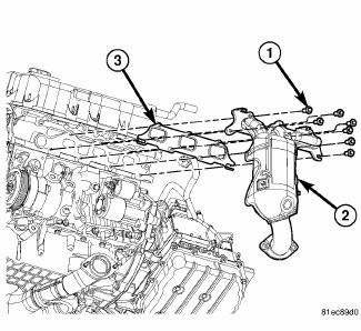
Fig. 300: Front Exhaust Maniverter Attaching Bolts
2. Install a new gasket (3), the front maniverter (2), and the front exhaust maniverter attaching bolts (1).
Tighten bolts to 23 Nm (17 ft. lb).
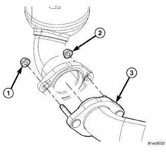
Fig. 301: Front Maniverter-To-Cross Under Fasteners
3. Install the front maniverter-to-crossunder fasteners (1) and (2). Tighten to 27 Nm (20 ft. lb.).
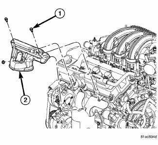
Fig. 302: Upper Maniverter Heat Shield
4. Install the upper maniverter heat shield (3) and the heat shield fasteners (1) and (2). Tighten fasteners to 12 Nm (106 in. lb.).
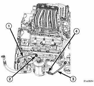
Fig. 303: Oxygen Sensors
5. Install the oxygen sensors (2) and (4). 41 Nm (30 ft. lbs.)
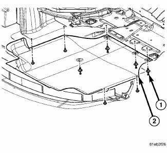
Fig. 304: Belly Pan
- - belly pan fasteners
- - belly pan
6. Install the belly pan (2).
7. Install the negative battery cable.
8. Install the engine cover.
 Manifold, exhaust, crossover
Removal
Fig. 287: Belly Pan
- belly pan fasteners
- belly pan
1. Remove the belly pan (2).
Fig. 288: Exhaust Extension Pipe
2. Remove the fasteners (1), and remove the exhaust extensio ...
 Manifold, exhaust, rear
Removal
Fig. 305: Belly Pan
- belly pan fasteners
- belly pan
1. Remove the belly pan (2).
Fig. 306: Oxygen Sensors
2. Remove the oxygen sensors (2) and (4).
Fig. 307: Exhaust Gas R ...
See also:
Specifications
BATTERY
The battery Group Size number, the Cold Cranking Amperage (CCA) rating, and
the Reserve Capacity (RC)
rating or Ampere-Hours (AH) rating can be found on the original equipment
battery la ...
Installation
2.0L TURBO DIESEL
Fig. 19: Generator Bushing
1. If reinstalling the old generator, install a generator mounting bolt and
tap bushing out slightly to ease
mounting of generator.
Fig. 20: Remo ...
Description
Fig. 1: Muffler/Exhaust Pipe Assembly - Single Tail Pipe
- INSULATOR
- MUFFLER/EXHAUST PIPE ASSEMBLY
- BAND CLAMP
The exhaust system on the 2.4L and 2.7L engine models consists of a front ...
