Dodge Journey: Insulator, engine mount, left
Removal
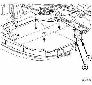
Fig. 228: Belly Pan
1. Disconnect and isolate the negative battery cable.
2. Remove throttle body air inlet hose and air cleaner housing assembly.
3. Remove the belly pan (2).
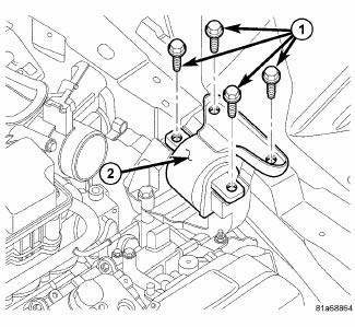
Fig. 229: Left Mount Vertical Bolts
4. Support transmission with floor jack and wooden block.
5. Remove the vertical bolts (1) from the left mount (2) to transmission bracket.
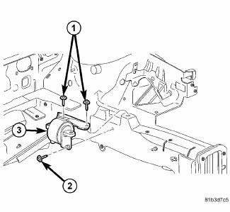
Fig. 230: Mount Isolator Bolts
6. Slightly lower transmission with floor jack to gain access to mount to frame rail fastener (2).
7. Remove mount isolator (3).
Installation
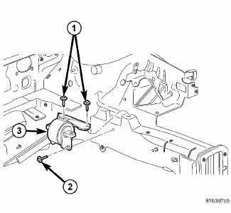
Fig. 231: Mount Isolator Bolts
1. Position mount isolator (3) in place, install bolts (1, 2) and tighten to 50 N.m (37 ft. lbs.).
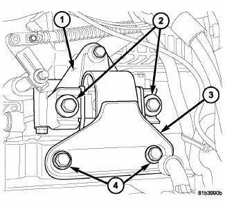
Fig. 232: Identifying Left Engine Mount
2. Raise transaxle into position, install bolts (2) and tighten to 98 N.m (72 ft. lbs.).
3. Remove floor jack and wooden block.
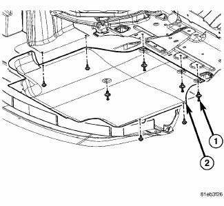
Fig. 233: Belly Pan
4. Install belly pan (2).
5. Install throttle body air inlet hose and air cleaner housing assembly.
6. Connect negative battery cable.
 Insulator, engine mount, front
Removal
1. Raise vehicle.
Fig. 222: Belly Pan
- belly pan fasteners
- belly pan
2. Remove the belly pan (2).
Fig. 223: Front Engine Mount Through Bolt
3. Remove front mount to bracket ...
 Insulator, engine mount, rear
Removal
Fig. 234: Belly Pan
1. Remove throttle body air inlet hose and air cleaner housing assembly.
2. Raise the vehicle.
3. Remove the belly pan (2).
Fig. 235: Identifying Rear Mount B ...
See also:
ELECTRONIC SPEED CONTROL — IF EQUIPPED
When engaged, the Electronic Speed Control takes over
the accelerator operation at speeds greater than 25 mph
(40 km/h).
The Electronic Speed Control lever is located on the right
side of the stee ...
MAINTENANCE SCHEDULE
The oil change indicator system will remind you that it is
time to take your vehicle in for scheduled maintenance.
On Electronic Vehicle Information Center (EVIC)
equipped vehicles “Oil Change Re ...
MEDIA CENTER 130 (RES) — AM/FM STEREO RADIO WITH CD PLAYER (MP3 AUX JACK)
NOTE: The radio sales code is located on the lower right
side of the radio faceplate.
RES Radio
Operating Instructions — Radio Mode
NOTE: The ignition switch must be in the ON or ACC
position ...
