Dodge Journey: Rod, piston and connecting
Description
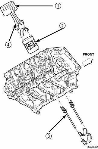
Fig. 206: Piston & Connecting Rod
- - "F" TOWARD FRONT OF ENGINE
- - RING COMPRESSOR
- - SPECIAL TOOL 8189
- - OIL SQUIRT HOLE
The pistons (1) are made of a high strength aluminum alloy with an anodized top ring groove. Piston skirts are coated with a solid lubricant for scuff resistance. The connecting rods are made of powdered metal with a "fractured cap" design. The connecting rod attaches to the piston with a full floating pin retained by lock rings.
The piston and connecting rod are serviced as an assembly.
Standard Procedure
FITTING PISTONS
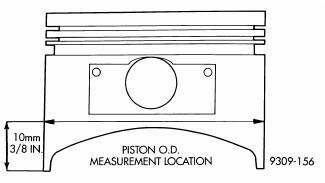
Fig. 207: Piston Measurements
The pistons have been cast and machined to one size and weight. The piston and rod assemblies are matched to weigh the same for engine balance.
Piston and cylinder wall must be clean and dry. Piston diameter should be measured 90 degrees to piston pin.
Cylinder bores should be measured halfway down the cylinder bore and transverse to the engine crankshaft center line. Pistons and cylinder bores should be measured at normal room temperature, 70ºF (21ºC).
PISTON PINS
The pistons have been cast and machined to one size and weight. The piston and rod assemblies are matched to weigh the same for engine balance.
The piston pin is full floating and is held in place by lock rings. Do Not switch pistons with other rods .
Pistons and connecting rods are serviced as an assembly for balance.
Removal
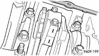
Fig. 208: Identify Connecting Rod to Cylinder
1. Remove top ridge of cylinder bores with a reliable ridge reamer before removing pistons from cylinder block. Be sure to keep tops of pistons covered during this operation. Pistons and connecting rods must be removed from top of cylinder block. When removing piston and connecting rod assemblies from the engine, rotate crankshaft so that each connecting rod is centered in cylinder bore.
NOTE: Connecting rod bearing caps are not interchangeable and should be marked before removing to ensure correct reassembly.
CAUTION: DO NOT use a number stamp or a punch to mark connecting rods.
Damage to connecting rod could occur.
2. Mark connecting rod and bearing cap positions using a permanent ink marker or scribe tool.
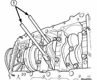
Fig. 209: Connecting Rod Guides
- - SPECIAL TOOL 8189 CONNECTING ROD GUIDES
CAUTION: Care must be taken not to damage the fractured rod and cap joint face surfaces, as engine damage may occur.
3. Remove connecting rod cap. Install Special Tool 8189 Connecting Rod Guides into the connecting rod being removed. Remove each piston and rod assembly out of cylinder bore.
NOTE: Be careful not to nick crankshaft journals.
4. After removal, install bearing cap on the mating rod to prevent damage to the fractured cap to rod surfaces.
Installation

Fig. 210: Piston & Connecting Rod
- - "F" TOWARD FRONT OF ENGINE
- - RING COMPRESSOR
- - SPECIAL TOOL 8189
- - OIL SQUIRT HOLE
1. Install the piston rings.
2. Before installing piston and connecting rod assemblies into the bore, ensure that compression ring gaps are staggered so that neither is in line with oil ring rail gap.
3. Before installing the ring compressor, make sure the oil ring expander ends are butted and the rail gaps are located properly.
4. Immerse the piston head and rings in clean engine oil, slide the ring compressor over the piston and tighten with the special wrench. Ensure position of rings does not change during this operation.
CAUTION: Ensure the hole in bearing half aligns with hole in connecting rod, as damage to engine may occur.
5. Position bearing onto connecting rod. Ensure that hole in bearing half is aligned to hole in connecting rod.
Lubricate bearing surface with clean engine oil.
6. Install Special Tools 8189 Connecting Rod Guides into connecting rod.
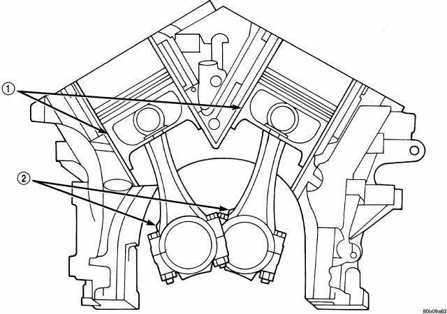
Fig. 211: Piston & Connecting Rod Positioning (Front View of Engine)
- - MAJOR THRUST SIDE OF PISTON
- - OIL SQUIRT HOLE
7. The pistons are marked on top with an arrow and with an "F" (Front) above the pin boss. These marks must be pointing toward the front of engine on both cylinder banks. The connecting rod oil squirt hole (2) faces the major thrust (right) side of the block.
8. Rotate crankshaft so that the connecting rod journal is on the center of the cylinder bore. Insert rod and piston into cylinder bore and guide rod over the crankshaft journal.
CAUTION: Do Not interchange piston assemblies bank to bank, as engine damage may occur.
9. Tap the piston down in cylinder bore, using a hammer handle. At the same time, guide connecting rod into position on connecting rod journal.
10. Lubricate rod bolts and bearing surface with engine oil. Install connecting rod cap and bearing. Tighten bolts to 27 N.m (20 ft. lbs.) Plus 1/4 turn.
 Ring(s), piston
Standard Procedure
PISTON RING FITTING
Fig. 200: CHECK GAP ON PISTON RINGS
- FEELER GAUGE
1. Wipe cylinder bore clean. Insert ring and push down with piston to ensure
it is square in bore ...
 Seal, crankshaft oil, front
Removal
Fig. 212: Crankshaft Front Oil Seal - Removal
- SPECIAL TOOL 6771
1. Remove crankshaft vibration damper.
2. Install Special Tool 8194, Insert into crankshaft nose. Remove seal us ...
See also:
Insulator, engine mount, rear
Removal
Fig. 234: Belly Pan
1. Remove throttle body air inlet hose and air cleaner housing assembly.
2. Raise the vehicle.
3. Remove the belly pan (2).
Fig. 235: Identifying Rear Mount B ...
VEHICLE IDENTIFICATION NUMBER
The Vehicle Identification Number (VIN) is on the left
front corner of the instrument panel and is visible from
outside of the vehicle through the windshield. This
number also appears on the Automo ...
Speaker
OPERATION
Two wires connected to each speaker, one feed circuit (+) and one return
circuit (-), allow the audio output signal electrical current to flow through
the voice coil. The wiring informa ...
