Dodge Journey: Damper, vibration
Removal

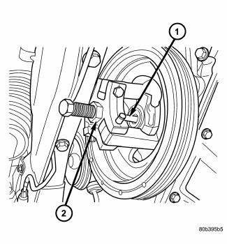
Fig. 196: Vibration Damper - Removal
- - SPECIAL TOOL 8454 PULLER
- - SPECIAL TOOL 8194 INSERT
1. Disconnect negative battery cable.
2. Remove right front wheel and belt splash shield.
3. Remove accessory drive belts.
4. Remove damper bolt.
5. Remove damper by using Special Tools 8194 Insert and 8454 Puller (1).
Installation

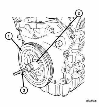
Fig. 197: Vibration Damper - Installation
- - VIBRATION DAMPER
- - SPECIAL TOOL 6792-1
- - SPECIAL TOOL 8179
1. Install damper using Special Tools 8179 (3) Screw, with Nut and Thrust Bearing from 6792, and 6792-1 Installer (2).
2. Install damper center bolt. Tighten center bolt to 170 N.m (125 ft. lbs.).
3. Install accessory drive belts.
4. Install belt splash shield and right front wheel.
5. Lower vehicle.
6. Connect negative battery cable.
 Crankshaft
Description
The crankshaft is constructed of a forged micro alloy steel. The six throw,
nine counterweight crankshaft is
supported by four select fit main bearings with the number three serving as ...
 Flexplate
Removal
Fig. 198: Flex Plate
1. Remove transmission.
2. Remove flex plate attaching bolts (2).
3. Remove backing plate (3) and flex plate (1).
Installation
Fig. 199: FLEX PLATE
1. Posit ...
See also:
Removal
1. Raise and support the vehicle.
NOTE: Perform 2 through 5 on each side of the vehicle to complete pad
set
removal.
Fig. 117: TIRE AND WHEEL MOUNTING
2. Remove the wheel mounting nuts ...
Cleaning, Inspection
CLEANING
Drain cooling system and refill with clean water. Refer to drain and fill
procedures in this service information .
Run engine with radiator cap installed until upper radiator hose is ho ...
Removal
WARNING: Disable the airbag system before attempting any steering
wheel, steering
column, or instrument panel component diagnosis or service. Disconnect
and isolate the battery negati ...
