Dodge Journey: Bearing(s), crankshaft, main
Standard Procedure
CRANKSHAFT MAIN BEARING FITTING
Fig. 169: Cylinder Block Main Bore Grade Marking
The grade marks for the cylinder block main bearing bore grade is located on the pan rail just below the left side engine mount bracket. These marks are read left to right, corresponding to main bore 1, 2, 3, 4.
Fig. 170: Crankshaft Main Journal Grade Marking Location
The main bearings are "select fit" to achieve proper oil clearances. For main bearing selection, the block and crankshaft have grade identification marks.
The grade marks for the crankshaft are located on the rearmost crankshaft counter weight as shown in illustration. The crankshaft journal grade marks are read left to right, corresponding with journal number 1, 2, 3, 4.
MAIN BEARING SELECTION CHART-2.7L
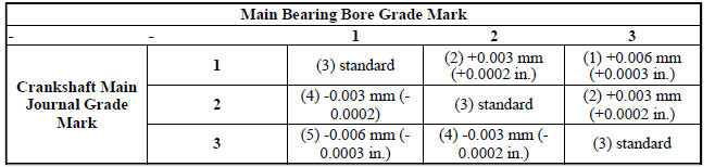
Refer to the selection chart to properly select the main bearings. For an example, if the main bore grade is 3 and the journal grade is 2, the proper select fit bearing would be (2) +0.003 mm (+0.0002 in.).
Fig. 171: Main Bearing Grade Marks
- - LOWER MAIN BEARING
- - UPPER MAIN BEARING
- - OIL FEED HOLE AND GROOVE
- - GRADE SELECTION INK MARKS
NOTE: Service main bearings have a number from 1-5 marked in ink on the bearing surface. For verification, use the MAIN BEARING SELECTION CHART-2.7L for number to size identification.
The upper main bearing has a oil feed hole and a center groove to allow lubrication of the main journal and must be properly positioned in the block.
NOTE: Although cylinder bores are graded for size, there is only one piston size.
 Bearing(s), connecting rod
Standard Procedure
CONNECTING ROD AND BEARING FITTING
CONNECTING ROD BEARING
Fig. 166: Checking Connecting Rod Bearing Clearance-Typical
Fit all connecting rods on one bank until complete.
Th ...
 Cover, structural dust
Removal
Fig. 172: Belly Pan
1. Raise and secure the vehicle on a hoist.
2. Remove the belly pan (2), if equipped.
Fig. 173: Front Engine Mount Through Bolt
3. Remove the fore/aft crossmemb ...
See also:
Seal, input flange
REMOVAL
Fig. 80: Removing /Installing Propeller Shaft
NOTE: Rubber coupler is part of the propeller shaft assembly. Removing
coupler from
propeller shaft will result in vibration/balance i ...
PUBLICATION ORDER FORMS
To order the following manuals, you may use either the
website or the phone numbers listed below. Visa, Mastercard,
American Express, and Discover orders are accepted.
If you prefer mailing your pa ...
Lamp, fog, front
REMOVAL
BULB
CAUTION: Do not contaminate the bulb glass by touching it with
your fingers or by
allowing it to contact other oily surfaces. Shortened bulb life will
result.
...
