Dodge Journey: Installation
2.0L TURBO DIESEL
Fig. 19: Generator Bushing
1. If reinstalling the old generator, install a generator mounting bolt and tap bushing out slightly to ease mounting of generator.
Fig. 20: Removing/Installing Generator
2. Install generator.
Fig. 21: Generator Lower Mounting Bolt
3. Loosely install lower generator mounting bolt.
4. Install upper generator mounting bolt.
5. Tighten generator mounting bolts to 54 N.m (40 ft. lbs.).
Fig. 22: Right Engine Mount
6. If removed, install two engine mounting bolts (2) to right engine mount (1). Reposition ground strap (3) if required.
Fig. 23: Idler Pulley Bolt Location
7. Install idler pulley and tighten bolt.
Fig. 24: Idler Cap Location
8. Install idler bolt cap.
Fig. 25: Generator Cables
9. Connect battery cable to generator and tighten nut to 10 N.m (88.5 in. lbs.).
10. Connect electrical connector to generator.
11. Install accessory drive belt.
12. Reconnect negative battery cable.
13. Install engine cover.
2.4L
Fig. 26: Removing/Installing Generator
1. Position generator in order to move past the A/C compressor and up toward generator mounting bracket.
Fig. 27: Identifying Generator Pulley
2. Continue moving generator up towards generator mounting bracket.
Fig. 28: Removing/Installing Generator
3. Install generator (1) to engine mounting bracket.
4. Install lower mounting bolt (2) and upper mounting bolt (3) to generator (1). Tighten bolts to 61 N.m (45 ft. lbs.).
Fig. 29: Removing/Installing Idler Pulley
5. Install lower idler pulley and bolt. Tighten bolt to 50 N.m (37 ft. lbs.).
Fig. 30: 2.4L Generator Electrical Connector
6. Connect field wire connector (4) into generator.
7. Install B+ terminal (3) and nut (2) to generator mounting stud. Tighten nut to 10 N.m (88.5 in. lbs.) 8. Snap plastic protective cover (1) to B+ terminal.
Fig. 31: Identifying A/C Compressor
9. Install A/C compressor.
CAUTION: Never force a belt over a pulley rim using a screwdriver. The synthetic fiber of the belt can be damaged.
CAUTION: When installing a serpentine accessory drive belt, the belt MUST be routed correctly. The water pump will be rotating in the wrong direction if the belt is installed incorrectly, causing the engine to overheat. Refer to belt routing label in engine compartment, or refer to BELT, SERPENTINE .
10. Install drive belt.
Fig. 32: Removing/Installing Underbody Air Dam
11. Install right front wheelhouse splash shield. 12. Install underbody air dam.
13. Connect negative battery cable, tighten nut to 4.5 N.m (40 in. lbs.).
2.7L
Fig. 33: 2.7L Removing/Installing Generator
1. Install generator (1) to engine mounting bracket.
2. Install lower mounting bolt (2) and upper mounting bolt (3) to generator (1). Tighten bolts to 27 N.m (20 ft. lbs.).
Fig. 34: Alternator Electrical Connection
3. Connect field wire connector (4) into generator.
4. Install B+ terminal (3) and nut (2) to generator mounting stud. Tighten nut to 10 N.m (88.5 in. lbs.)
5. Snap plastic protective cover (1) to B+ terminal.
CAUTION: Never force a belt over a pulley rim using a screwdriver. The synthetic fiber of the belt can be damaged.
CAUTION: When installing a serpentine accessory drive belt, the belt MUST be routed correctly. The water pump will be rotating in the wrong direction if the belt is installed incorrectly, causing the engine to overheat. Refer to belt routing label in engine compartment, or refer to BELT, SERPENTINE .
6. Install drive belt.
7. Connect negative battery cable, tighten nut to 4.5 N.m (40 in. lbs.).
3.5L
Fig. 35: 3.5L Removing/Installing Generator
1. Install generator (1) to engine mounting bracket.
2. Install long mounting bolt (2) and short mounting bolt (3) to generator (1). Tighten bolts to 42 N.m (31 ft.lbs.).
Fig. 36: 3.5L Generator Electrical Connector
3. Connect field wire connector (1) into generator.
4. Install B+ terminal (2) and nut (3) to generator mounting stud. Tighten nut to 10 N.m (88.5 in. lbs.)
5. Snap plastic protective cover (4) to B+ terminal.
6. Install drive belt.
7. Connect negative battery cable, tighten nut to 4.5 N.m (40 in. lbs.).
Fuses & Circuit Breakers
IDENTIFICATION
CAUTION: When battery is disconnected, vehicle computer and memory systems may lose memory data. Driveability problems may exist until computer systems have completed a relearn cycle.
TOTALLY INTEGRATED POWER MODULE
For integrated power module location, see Fig. 1.
Fig. 1: Locating Totally Integrated Power Module
Fig. 2: Identifying Totally Integrated Power Module Components
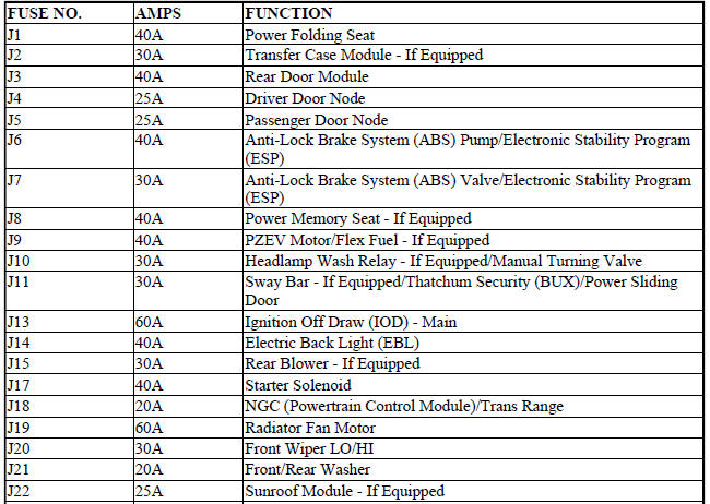
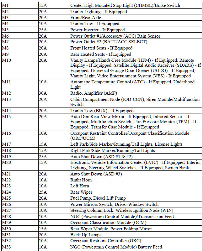
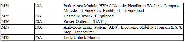
Totally Integrated Power Module Fuses
 Removal
2.0L TURBO DIESEL
Fig. 2: Generator Cables
1. Remove engine cover.
2. Disconnect and isolate the negative battery cable.
3. Remove accessory drive belt.
4. Disconnect battery cable fro ...
 Engine
...
See also:
Switch, heated seat
DESCRIPTION
Fig. 10: Locating Accessory Switch Bank Module
Two heated seat switches are located in the center stack of the instrument
panel. The switches are located on the
outer edges of the A ...
Sensor, mass air flow (MAF)
Removal
Fig. 10: MASS AIR FLOW SENSOR
1. Disconnect air flow sensor electrical connector (4).
2. Remove constant tension clamps (1), (2) securing the air flow sensor (3).
3. Remove air flow ...
Installation
Fig. 137: Rear Mount Bracket
1. If transmission brackets were removed or transmission was replaced install
the rear mount bracket and
tighten (1) to 100 N.m (74 ft. lbs.).
Fig. 138: Front Mou ...
