Dodge Journey: Removal
2.0L TURBO DIESEL
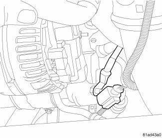
Fig. 2: Generator Cables
1. Remove engine cover.
2. Disconnect and isolate the negative battery cable.
3. Remove accessory drive belt.
4. Disconnect battery cable from generator.
5. Disconnect electrical connector from generator.
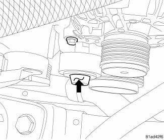
Fig. 3: Idler Cap Location
6. Remove cap from idler pulley mounting bolt.
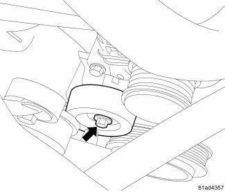
Fig. 4: Idler Pulley Bolt Location
7. Remove idler pulley bolt.
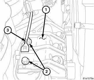
Fig. 5: Right Engine Mount
8. It may be necessary to remove the two engine mounting bolts (2) from the right engine mount (1) and reposition engine in order to remove the lower generator mounting bolt. Reposition ground strap (3) if required.
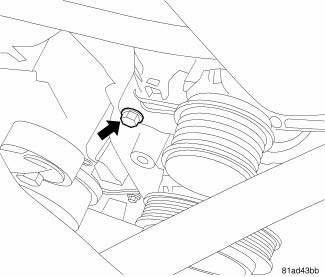
Fig. 6: Generator Lower Mounting Bolt
9. Remove lower generator mounting bolt.
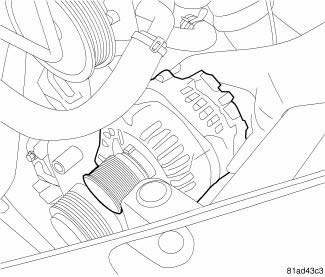
Fig. 7: Removing/Installing Generator
10. Remove upper generator mounting bolt.
11. Remove generator.
2.4L
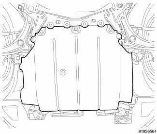
Fig. 8: Removing/Installing Underbody Air Dam
CAUTION: Disconnect the negative battery cable before removing the battery output wire from generator. Failure to do so can result in injury or damage to electrical system.
1. Disconnect and isolate negative battery cable.
2. Remove underbody air dam.
3. Remove right front wheelhouse splash shield.
4. Remove generator drive belt.
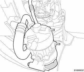
Fig. 9: Identifying A/C Compressor
NOTE: Do not disconnect the A/C lines when relocating the A/C compressor.
CAUTION: Support the A/C compressor when relocating. Failure to properly support the A/C compressor can cause damage to the lines and or seals. This can cause a leak in the A/C system.
5. Relocate A/C compresso
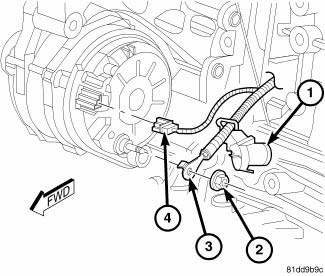
Fig. 10: 2.4L Generator Electrical Connector
CAUTION: Never force a belt over a pulley rim using a screwdriver. The synthetic fiber of the belt can be damaged.
6. Unsnap plastic protective cover (1) from B+ mounting stud.
7. Remove B+ terminal mounting nut (2) and B+ terminal (3) from generator.
8. Disconnect field wire electrical connector (4) by pushing on connector tab.
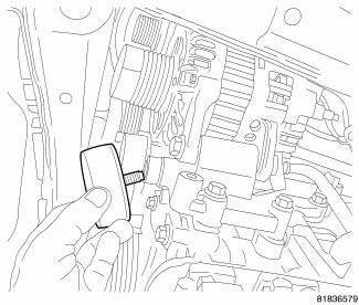
Fig. 11: Removing/Installing Idler Pulley
9. Remove bolt and lower idler pulley.
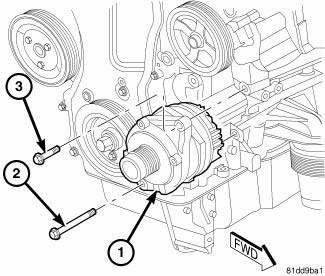
Fig. 12: Removing/Installing Generator
10. Remove upper mounting bolt (3) from generator (1).
11. Remove lower mounting bolt (2) from generator (1).
12. Remove generator (1) from engine mounting bracket.
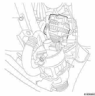
Fig. 13: Identifying Generator Pulley
13. Rotate generator so that the pulley faces down.
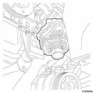
Fig. 14: Removing/Installing Generator
14. Position generator in order to move past the A/C compressor and out of vehicle.
2.7L
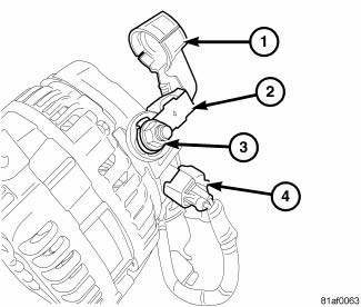
Fig. 15: Alternator Electrical Connection
CAUTION: Disconnect the negative battery cable before removing the battery output wire from generator. Failure to do so can result in injury or damage to electrical system.
1. Disconnect and isolate negative battery cable.
CAUTION: Never force a belt over a pulley rim using a screwdriver. The synthetic fiber of the belt can be damaged.
2. Remove generator drive belt.
3. Unsnap plastic protective cover (1) from B+ mounting stud.
4. Remove B+ terminal mounting nut (2) and B+ terminal (3) at top of generator.
5. Disconnect field wire electrical connector (4) by pushing on connector tab.
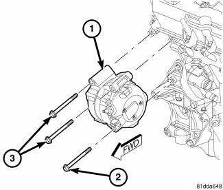
Fig. 16: 2.7L Removing/Installing Generator
6. Remove upper mounting bolts (3) from generator (1).
7. Remove lower mounting bolt (2) from generator (1).
8. Remove generator (1) from engine mounting bracket.
3.5L
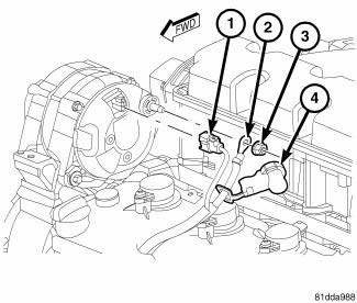
Fig. 17: 3.5L Generator Electrical Connector
CAUTION: Never force a belt over a pulley rim using a screwdriver. The synthetic fiber of the belt can be damaged.
1. Disconnect and isolate negative battery cable.
2. Remove generator drive belt.
3. Unsnap plastic protective cover (4) from B+ mounting stud.
4. Remove B+ terminal mounting nut (3) and B+ terminal (2) at top of generator.
5. Disconnect field wire electrical connector (1) by pushing on connector tab.
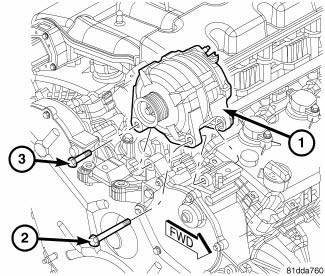
Fig. 18: 3.5L Removing/Installing Generator
6. Remove short mounting bolt (3) from generator (1).
7. Remove long mounting bolt (2) from generator (1).
8. Remove generator (1) from engine mounting bracket.
 Description, Operation
DESCRIPTION
The generator is belt-driven by the engine. It is serviced only as a complete
assembly. If the generator fails for
any reason, the entire assembly must be replaced. The generator produ ...
 Installation
2.0L TURBO DIESEL
Fig. 19: Generator Bushing
1. If reinstalling the old generator, install a generator mounting bolt and
tap bushing out slightly to ease
mounting of generator.
Fig. 20: Remo ...
See also:
Specifications
BATTERY
The battery Group Size number, the Cold Cranking Amperage (CCA) rating, and
the Reserve Capacity (RC)
rating or Ampere-Hours (AH) rating can be found on the original equipment
battery la ...
Grid, defogger, rear
STANDARD PROCEDURE
GRID LINE AND TERMINAL REPAIR
WARNING: Materials contained in the Repair Kit (Part Number
04549275) may cause
skin or eye irritation. The kit contains epoxy resin an ...
Cam, turn signal cancel
DESCRIPTION
The turn signal cancel cam is concealed within the clockspring case on the
steering column. The turn signal
cancel cam consists of integral eccentrics on the outer circumference of the ...
