Dodge Journey: Removal, Installation
REMOVAL
WARNING: To protect the hands from battery acid, a suitable pair of heavy duty rubber gloves should be worn when removing or servicing a battery.
Safety glasses also should be worn.
WARNING: Remove metallic jewelry to avoid injury by accidental arcing of battery current.
CAUTION: The negative battery cable remote terminal (2) must be disconnected and isolated from the remote battery post (1) prior to service of the vehicle electrical systems. The negative battery cable remote terminal can be isolated by using the supplied isolation hole (3) in the terminal casing.

Fig. 12: Identifying Battery Cables & Terminals
1. Disconnect and isolate the negative battery cable remote terminal from the remote battery post.
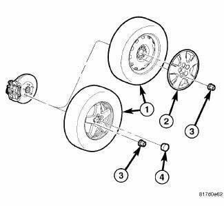
Fig. 13: TIRE AND WHEEL MOUNTING
2. Remove the left front wheel and tire assembly.
NOTE: Gasoline battery shown in illustration, diesel battery similar.

Fig. 14: Push-Puns & Splash Shield
3. Remove the push pins (1) and remove the left front wheelhouse splash shield (2).

Fig. 15: Battery, Bracket & Nut
4. Loosen the nut (1) and position the battery hold down bracket out of the way (3).

Fig. 16: Battery And Pinch Clamp Bolts
5. Loosen the pinch clamp bolts and position aside the battery cable clamps from the battery.

Fig. 17: Battery
6. Remove the battery (1) from the battery tray (2).
INSTALLATION
WARNING: To protect the hands from battery acid, a suitable pair of heavy duty rubber gloves should be worn when removing or servicing a battery.
Safety glasses also should be worn.
WARNING: Remove metallic jewelry to avoid injury by accidental arcing of battery current.
CAUTION: The negative battery cable remote terminal (2) must be disconnected and isolated from the remote battery post (1) prior to service of the vehicle electrical systems. The negative battery cable remote terminal can be isolated by using the supplied isolation hole (3) in the terminal casing.
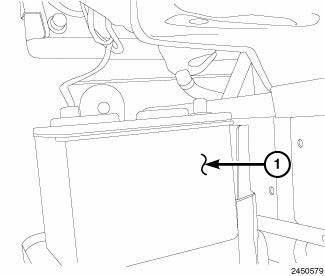
Fig. 18: Battery
1. Install the battery (1) into the battery tray (2).
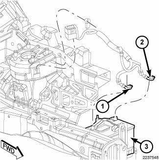
Fig. 19: Battery And Pinch Clamp Bolts
2. Install the battery terminal pinch clamps (1, 2) onto the battery posts.
Tighten the pinch clamp nut to 17.5 N.m (13 in. lbs.)
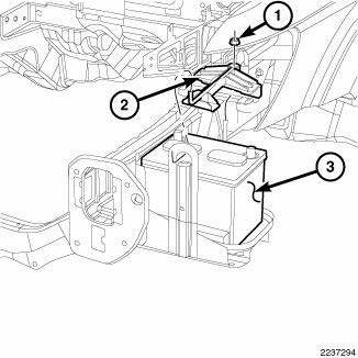
Fig. 20: Battery, Bracket & Nut
3. Position back the battery hold down bracket (3) and install the bracket nut (1).
Tighten the pinch clamp nut to 55 N.m (40 ft. lbs.)
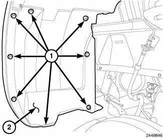
Fig. 21: Push-Puns & Splash Shield
4. Install the left front wheelhouse splash shield (2) and push pins (1).

Fig. 22: TIRE AND WHEEL MOUNTING
5. Install the left front wheel and tire assembly.
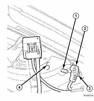
Fig. 23: Identifying Battery Cables & Terminals
6. Install the negative battery cable remote terminal onto the remote battery post.
Tighten the nut to 28 N.m (9.5 in. lbs.)
 Standard procedure
SPIRAL CELL BATTERY CHARGING
WARNING: Never exceed 14.4 volts when charging a spiral cell
battery. Personal
injury and/or battery damage may result.
Vehicles equipped with a diese ...
 Cables, battery
...
See also:
Description, Operation
DESCRIPTION
Several combinations of radio receivers and speaker systems are offered. The
audio system uses an ignition
switched source of battery current so that the system will only operate when ...
Cover(s), engine timing
Removal
Fig. 349: FRONT SPLASH SHIELDS
1. Disconnect and isolate negative battery cable.
2. Drain cooling system.
3. Remove coolant pressure container.
4. Remove right front wheel and bel ...
Standard procedure
PCM/ECM REPROGRAMMING - GAS
Follow the instructions in order.
OBTAINING DIAGNOSTIC TROUBLE CODES
BULB CHECK
Key on: Bulb illuminated until vehicle starts, as long as all once per trip
(readiness ...
