Dodge Journey: Installation

Fig. 67: Seal Protector
- - HALFSHAFT
- - SEAL PROTECTOR
1. Install driveline module to transmission jack. Secure module to jack.
2. Using Seal Protector 9099 (2), load halfshafts to differential, one side at a time. Clean tool and seal area to prevent debris intrusion.
Fig. 68: Support Module With Jack
- - DRIVELINE MODULE
- - TRANSMISSION JACK
3. Raise driveline module (1) into position.
Fig. 69: Removing /Installing Propeller Shaft
4. Align marks (4) on propeller shaft rubber coupler (1) to rear axle input flange (5).
5. Install three rear propeller shaft to rear axle retaining bolts (3) but do not tighten at this time.

Fig. 70: RDA To Crossmember Bolts
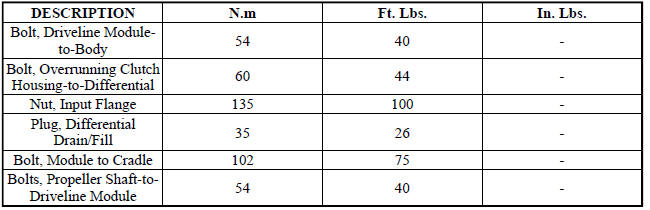
6. Install the RDA - to - crossmember mounting bolts (1) and tighten to 102 N.m (75 ft. lbs.).
Fig. 71: Rear RDA Module-To-Crossmember Bolt
7. Install the rear RDA - to - crossmember mounting bolt (2) to 102 N.m (75 ft. lbs.)
8. Tighten propeller shaft-to-driveline module bolts to 58 N.m (43 ft.lbs.).
9. Raise exhaust system into position and install hanger/brackets.
10. Fill differential with 0.7L (0.74 Quarts) of Mopar Gear and Axle Lubricant (75W-90).
SPECIFICATIONS
SPECIAL TOOLS
Fig. 72: Flange Wrench, C-3281
Fig. 73: Installer 8493
Fig. 74: Installer 9231A
Fig. 75: Protector, 9099
Fig. 76: Universal Handle C-4171
 Removal
Fig. 60: Support Module With Jack
- DRIVELINE MODULE
- TRANSMISSION JACK
NOTE: Rear suspension and drivetrain design require this procedure to
be performed
on a "drive-on" ...
 Case assembly, differential
DESCRIPTION
The differential gear system divides the torque between the axle shafts. It
allows the axle shafts to rotate at
different speeds when turning corners.
Each differential side gear is s ...
See also:
REAR WINDOW FEATURES
Rear Window Wiper/Washer
The rear window wiper/washer control is located on the
right side of the steering column.
Rear Window Wiper/Washer Control
Rotate the switch upward to the
“On” pos ...
Lamp, fog, front
REMOVAL
BULB
CAUTION: Do not contaminate the bulb glass by touching it with
your fingers or by
allowing it to contact other oily surfaces. Shortened bulb life will
result.
...
Belt, serpentine
Description
Fig. 15: ACCESSORY DRIVE BELT - WORLD ENGINE
- POWER STEERING PUMP
- ACCESSORY DRIVE BELT
- GENERATOR
- CRANKSHAFT PULLEY
- LOWER IDLER PULLEY
- CRANKSHAFT PULLEY
- WATE ...
