Dodge Journey: Installation
Fig. 40: Seal Protector
- - HALFSHAFT
- - SEAL PROTECTOR
1. Install halfshaft to hub/bearing assembly. Install hub nut and washer but do not tighten at this time.
2. Using Seal Protector 9099 (2) , install halfshaft (1) to differential assembly. Clean tool and seal area to prevent debris intrusion.
Fig. 41: Module Mounting Bolt
- - BOLT
- - DRIVELINE MODULE
3. Raise driveline module into position. Install module mounting bolt (1) .
Fig. 42: Module Mounting Bolts
- - BOLT (2)
- - DRIVELINE MODULE
4. Install remaining two module mounting bolts (2) .
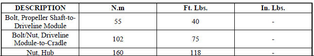
5. Torque module-to-cradle bolts to 102 N.m (75 ft. lbs.) 6. Torque the halfshaft/hub nut to 160 N.m (118 ft.lbs.).
7. Install wheel center cap.
8. Check and adjust differential fluid level.
SPECIFICATIONS

SPECIAL TOOLS
Fig. 43: Protector, 9099
 Removal
Fig. 35: Removing/Installing Halfshaft Nut
NOTE: Rear suspension and drivetrain design require this procedure to
be performed
on a "drive-on" hoist, as the front and rear suspensi ...
 Intermediate shaft, gas
REMOVAL
2.4L
1. Remove the right half shaft.
Fig. 44: Intermediate Shaft - 2.4L
2. Remove the three intermediate shaft bolts (1).
3. Remove the intermediate shaft (2).
2.7L
1. Remove the r ...
See also:
Pump, water
Description
2.4L
Fig. 80: WATER PUMP - WORLD ENGINE
- ACCESSORY DRIVE BELT
- WATER PUMP PULLEY
- WATER PUMP
The water pump (3) on the world engine is attached to the water pump adapter ...
Removal
1. Remove the engine cover.
2. Release fuel pressure.
3. Disconnect negative battery cable.
4. Drain cooling system.
5. Evacuate the A/C system using a suitable refrigerant recovery machi ...
DRIVING ON SLIPPERY SURFACES
Acceleration
Rapid acceleration on snow covered, wet, or other slippery
surfaces may cause the front wheels to pull erratically
to the right or left. This phenomenon occurs when
there is a differe ...
