Dodge Journey: Installation
WITH FOOT LEVER
1. Pass most of the front parking brake cable down through the access hole in the floor pan from inside the vehicle.
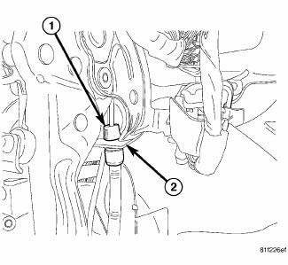
Fig. 195: CABLE HOUSING RETAINED IN LEVER
2. Insert the lever end of the front parking brake cable through the mounting hole in the parking brake lever (2). Slide it through until the cable retainer fingers on the end of the housing (1) lock in place. Make sure all fingers are engaged preventing removal of the cable from the bracket.
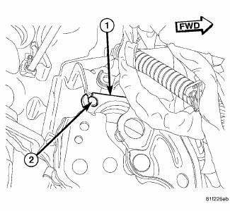
Fig. 196: CABLE BUTTON LOCATED IN LEVER
3. Pull the button on the end of cable strand out of housing and route the strand around the cable guide, then rotate the cable strand up and align the cable with the slot in lever mechanism (1). Slide the cable button (2) into the slot and rotate the cable down into mounted position with the cable inserted into the guide on the mechanism.
4. Slide any extra cable back into the cable housing. This can be easily done by pulling on the trailing end of the front cable strand that is now under the vehicle.
5. Install the front parking brake cable floor pan seal into the access hole in the floor pan.
6. Reposition the carpeting back down on the floor.
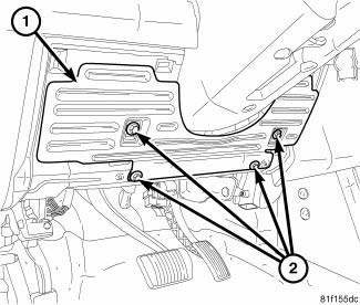
Fig. 197: STEERING COLUMN COVER REINFORCEMENT
7. Install the steering column cover reinforcement (1) using the four mounting screws (2).
8. Install the steering column opening cover.
9. Install the lower cowl trim.
10. Install the left front door opening sill scuff plate.
11. Raise and support the vehicle.

Fig. 198: PARKING BRAKE CABLE EQUALIZER
12. Pass the end of the front cable (5) through the hole in the end of the intermediate bracket (1). Press the cable housing retainer through the hole until the fingers on the retainer lock it into place.
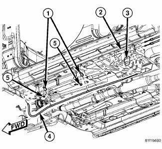
Fig. 199: CABLE MOUNTING TO UNDERBODY WITH FOOT LEVER
13. Install the cable routing clamps (1) over the metal sleeves on the front cable (4).
14. Position the front cable routing clamps over the studs on the underbody of the vehicle and install the nuts (5). Tighten the nuts to 6 N.m (55 in. lbs.).
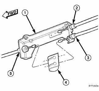
Fig. 200: PARKING BRAKE CABLE EQUALIZER
15. Reconnect the parking brake cable equalizer (4) and reset the cable tension.
16. Lower the vehicle.
17. Apply and release the parking brake lever (pedal) one time. This will seat the parking brake cables.
18. Check operation of parking brakes.
WITH HAND LEVER
1. Pass most of the front parking brake cable down through the access hole in the floor pan from inside the vehicle.
2. Install the front parking brake cable floor pan seal into the access hole in the floor pan.
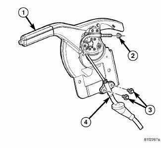
Fig. 201: CABLE MOUNTING TO HAND LEVER
3. Install the mounting screws (3) fastening the front cable (4) to the side of the parking brake lever (1).
Tighten the mounting screws to 28 N.m (21 ft. lbs.).
4. Route the cable strand around the lever cable guide and start the adjusting nut (2) on the end of the cable stud. Do not install the nut any further than having the threads flush with the top of the nut.
Otherwise, cable equalizer/bent nail tensioner installation later in this procedure could be difficult.
5. Slide any extra cable back into the cable housing.
6. Raise and support the vehicle.
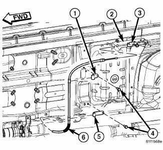
Fig. 202: CABLE MOUNTING TO UNDERBODY WITH HAND LEVER
7. Install the cable routing clamps (1, 5) over the metal sleeves on the front cable (6). Be sure to place the correct length clamp at the appropriate location.
8. Position the front cable routing clamps over the studs on the underbody of the vehicle and install the screws (4). Tighten the screws to 6 N.m (55 in. lbs.).
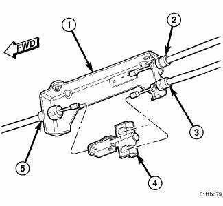
Fig. 203: CABLE EQUALIZER/TENSIONER
9. Pass the end of the front cable (5) through the hole in the end of the intermediate bracket (1). Press the cable housing retainer through the hole until the fingers on the retainer lock it into place.
10. Connect the parking brake cable equalizer/bent nail tensioner (4) to the three parking brake cables (2, 3, 5).
11. Remove any slack from the parking brake cables by pushing the front cable strand forward into the housing until slack is removed.
12. Lower the vehicle.
13. Reset the hand lever cable tension and verify check operation of the parking brake.
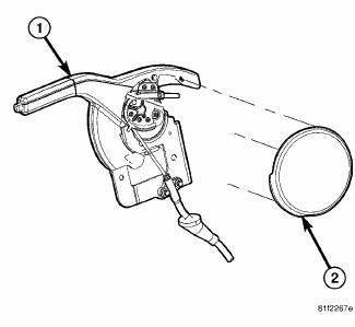
Fig. 204: HAND LEVER COVER MOUNTING
14. Install the cover on the side of the parking brake lever.
Fig. 205: CENTER CONSOLE
15. Install the floor center console.
 Removal
WITH FOOT LEVER
1. Release the parking brake.
2. Raise and support the vehicle.
3. Manually release the parking brake cable tension.
Fig. 186: PARKING BRAKE CABLE EQUALIZER
4. Collapse t ...

See also:
Switch, horn
REMOVAL
WARNING: On vehicles equipped with an airbag, refer to Restraint
SERVICE
INFORMATION article for warnings and cautions before servicing the horn
switch.
Fig. 3: Remov ...
Diagnosis and Testing
LOWER BALL JOINT
1. Raise the vehicle allowing the front suspension to hang.
2. Remove the tire and wheel assembly.
3. Using Dial Indicator C-3339A, or equivalent, attach the dial indicator mou ...
Assembly
CAUTION: Be certain to adjust the refrigerant oil level when
servicing the A/C
refrigerant system. Failure to properly adjust the refrigerant
oil level will prevent the A/C system fro ...
